Z06 Full Power Seats
(updated 11/16/22)
This modification allows the replacement of standard Z06 seats with full power seats and lumbar support
Z06 seats have power on the drivers side and a manual seat on the passenger side. After an 8500 mile road trip, my wife complained that the passenger seat was uncomfortable on some of the long days. When she drove, I tried out the passenger seat and the lack of adjustability was a problem for me as well. My buddy's 2007 LT3 Coupe has full power and lumbar support on both seats. That's what I wanted for my 2007 Z06 with Option 2LZ (heated seats).
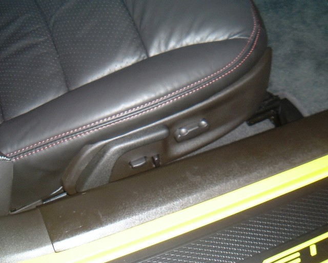
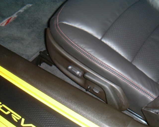
So I found a pair of new 2007 seats out of an LT3 coupe. They didn't have covers on them, but I wanted the Z06 covers anyway. The covers are pretty much the same, but the Z06 covers have a Z06 logo on the seat back and the passenger bottom cushion is cut out differently because the lack of switches on the side of the cushion. But the Z06 covers fit the seats exactly the same.
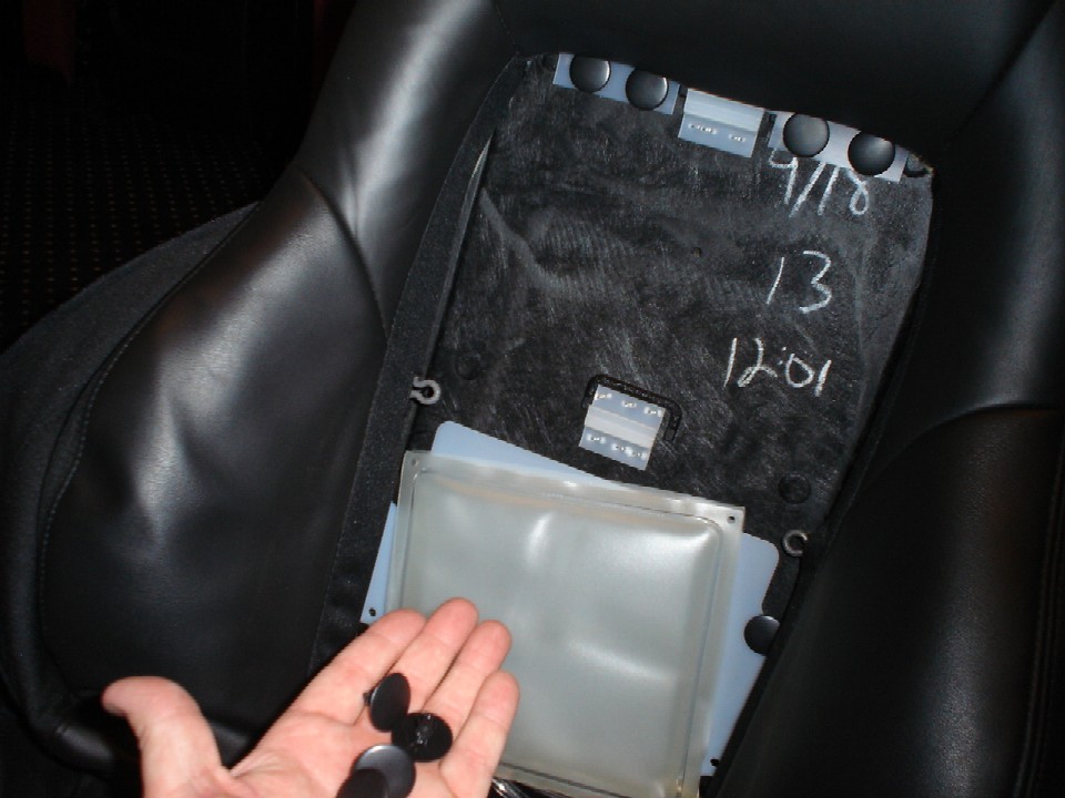
Here's a photo of the bottom of the Z06 drivers seat:
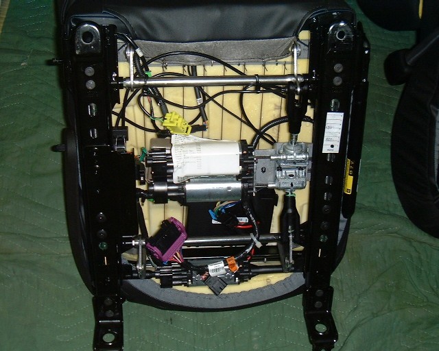
This seat is identical to the LT3 coupe drivers seat but it does not have the lumbar support module.
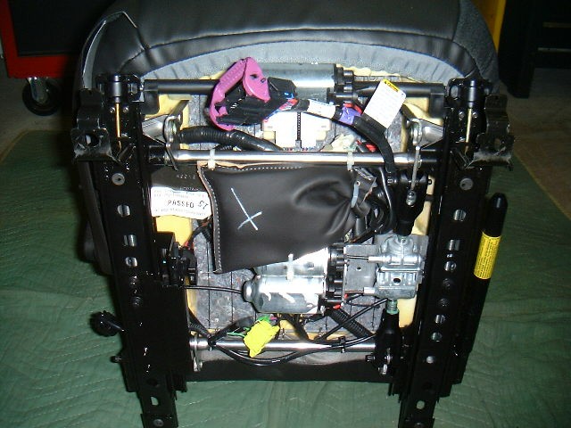
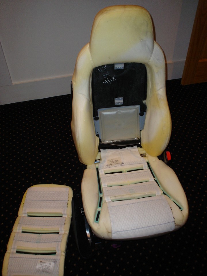
Now here's the Z06 passenger seat:
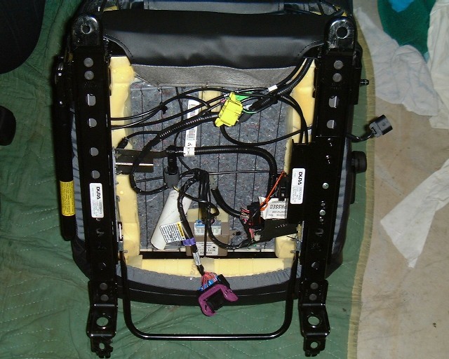
Note it's a lot less crowded with no motors, even though it has the heated seat option.
So I pulled the Z06 seats to replace them with the new LT3 seats, which I covered with the Z06 covers. And I found the first problem:
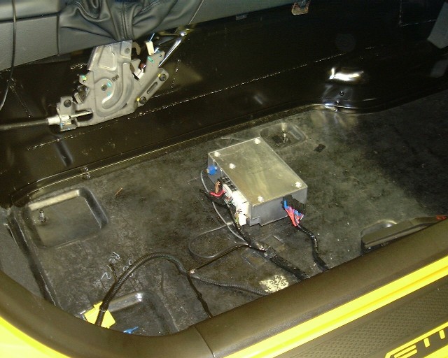
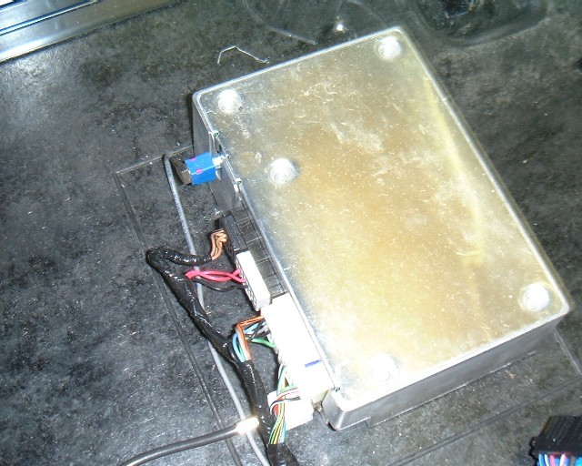
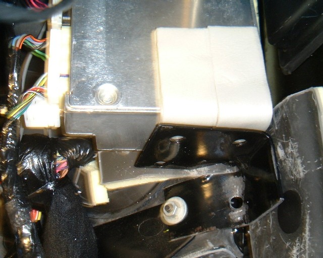
This is the passenger compartment with the carpet removed. Under the passenger seat on the Z06 is the Onstar module (known to Corvette engineers as the VCIM - Vehicle Communication Interface Module). In the standard Corvettes, the VCIM is in the right rear storage compartment. But because the Z06 battery is located there, the VCIM was moved to under the passenger seat.
With the Onstar module under the seat, there is no way to fit motorized LT3 seats. There is less than 1" clearance to the floor with the motorized seats and the Onstar module is 2 1/4" high. Once I saw the module there, I almost gave up on the motorized seat idea and thought I would just add the lumbar module to the standard manual Z06 seat.
But after thinking about alternative locations for the Onstar module, I found the ideal spot. The cables are too short to move the module towards the rear, but up above the Instrument Panel Fuse Block, to the right, is an empty area that will just accommodate the Onstar module. OK, first problem solved. Moving the module will allow me to install the motorized seat.
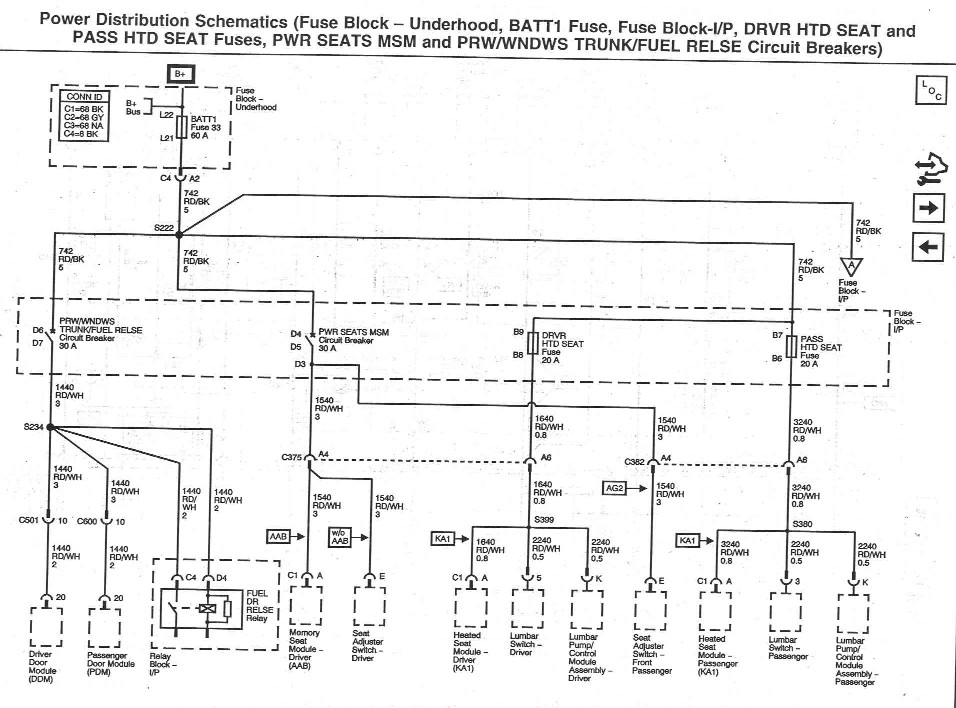
Now the second problem. Here is the schematic of part of the Power Distribution in the Corvette:
Updated 11/15/22
Take a close look at this. First note that each seat has a separate fuse and circuit for the heated seats. And power for the lumbar pump comes off of those same circuits. So if you have the heated seat option, you have power for the lumbar pumps. That's the good news. Now look at the Power Seat circuit breaker. This 30 amp breaker supplies power to both the drivers and the passenger seats for powering the seat motors. See Connection D3 just below the Circuit Breaker on the Schematic? That is the splice where wires to the drivers and passenger seat split. Unfortunately, on the Z06, this splice doesn't exist nor does the passenger seat wire. There is no wire for power to the passenger seat on the Z06. We need to create the D3 Splice and run a new wire for the passenger seat (see this later).
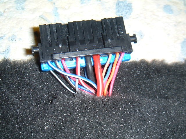
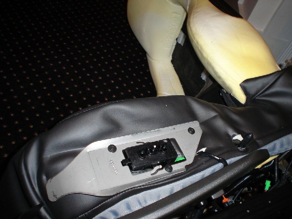
On the seat end, here is what the seat connector looks like:
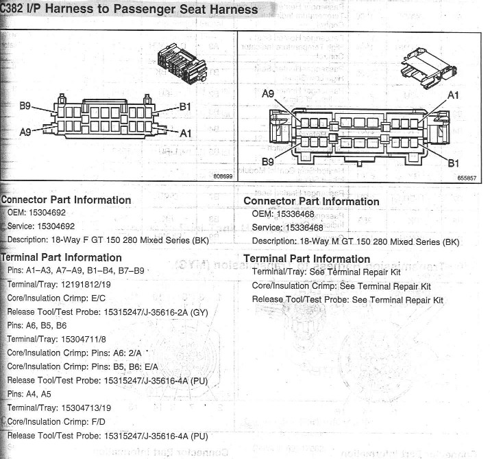
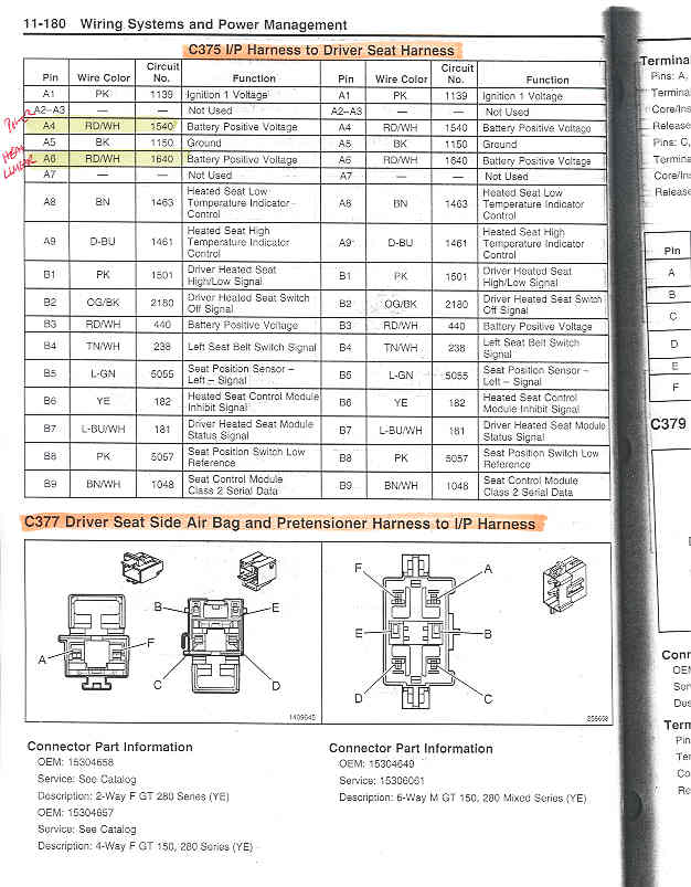
Now here are the pinouts for the connector:
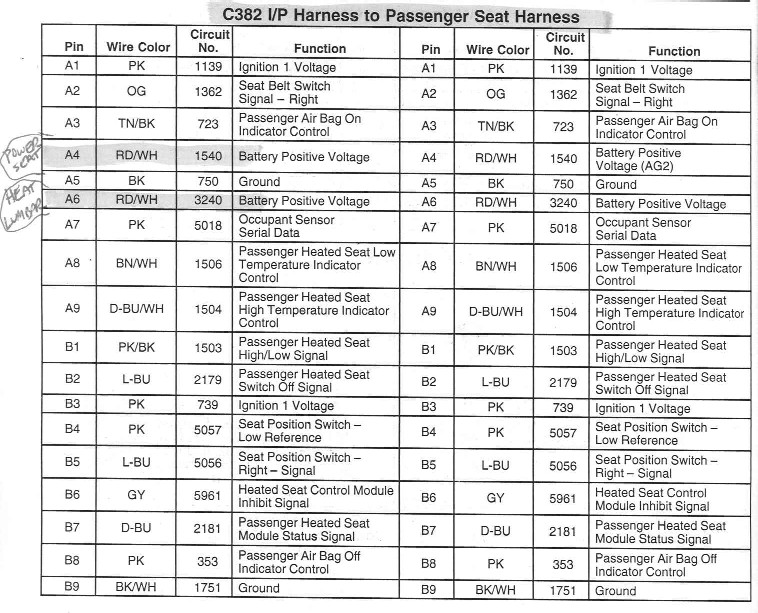
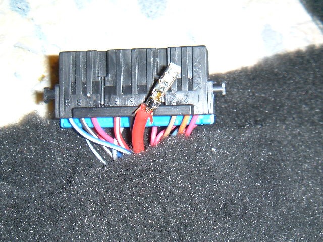
Notice Pin A4 provides the Circuit 1540 for the seat motor power. Connector C382 is the seat connector for the passenger seat. But the Z06 passenger seat connector C382 has a missing pin at location A4 - there is no wire from the circuit breaker:
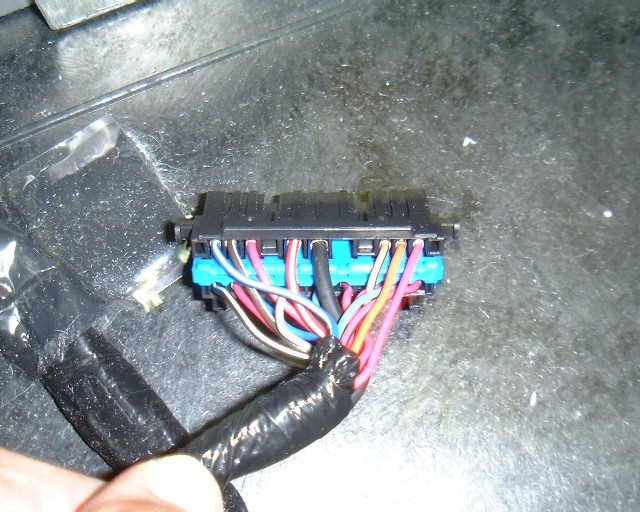
See the missing wire just to the right of the large black (ground) wire? That's where Pin A4 is supposed to be.
OK, the solution to these two problems:
First, I had to move the Onstar module. The box itself is stuck to the floor with a very sticky tape. By twisting the module, it isn't hard to get it unstuck and the tape cleaned off.
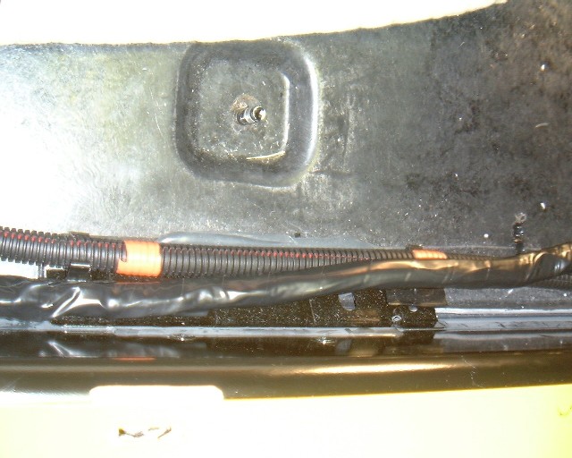
But that is the easy part. The wire harness is routed over to the right sill plate where it enters a main wire harness running along the sill. The bundle of wires from there to the Onstar module is too short to move the module up under the instrument panel. So we've got to untape the main harness and pull the Onstar wire bundle from the main harness. So first remove the sill trim plate:
At the rear of the trim, near the back of the door, pull straight up carefully. The three clips along the trim and one up on the curve will pop out, allowing you to remove the trim. This also makes it easier to remove the carpet as well. The carpet can be pulled down from the center console area by pulling on the carpet in the middle of the passenger area. Once this sill plate is out, carpet removal is pretty easy. With the sill trim off, you'll see the main wiring harness. Start untaping the main harness from where the Onstar module bundle enters:

For the new Onstar module location, look up under the dash, above the fuse panel. You'll see two round plastic push pins that you can remove easily with a flat screwdriver. These hold this removable panel in place:
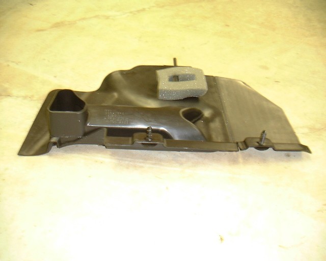
The two plastic pins are closest to you, and the back of the panel (towards the firewall) is just supported by a single plastic pin. Pull down this panel and remove it.
Now look way up under the dash on the right side of the car and you'll see an area that is just big enough to accommodate the Onstar module. I made a bracket to hold the module in place, letting it rest on some foam tape at the top and at the bottom. Basically, you have to improvise something to hold the module in place - it fits there just fine, but it won't stay without something holding it up there. Here's my bracket:
I routed the wires down and along the sill plate after I retaped the harness:
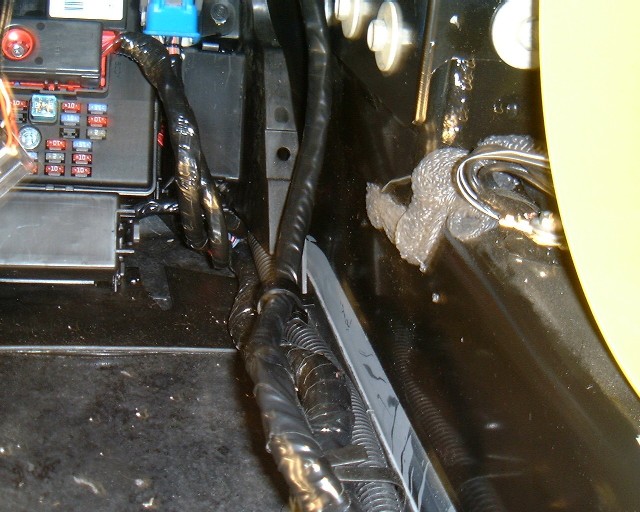
OK, that solved the first problem - moving the Onstar module.
Now, onto the second problem:
Getting a Power Wire to the Passenger Seat.
Take a look at the fuse block:

On the lower right, behind that big black wire bundle, is a plastic cover protecting the circuit breakers. For reference, see the fuse and circuit breaker locations on the fuse block diagram on the footwell fuse cover. Once you pull off the plastic cover, you'll see the 30 amp circuit breaker for the Power Seats just above the 30 breaker for the Power Windows.
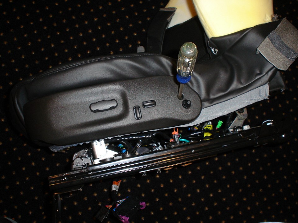
Remove the Fuse Panel by removing the three 7 mm screws holding it in place. Once loose, pull the fuse panel to the left and you can unclip the circuit breaker panel with two clips at the bottom:
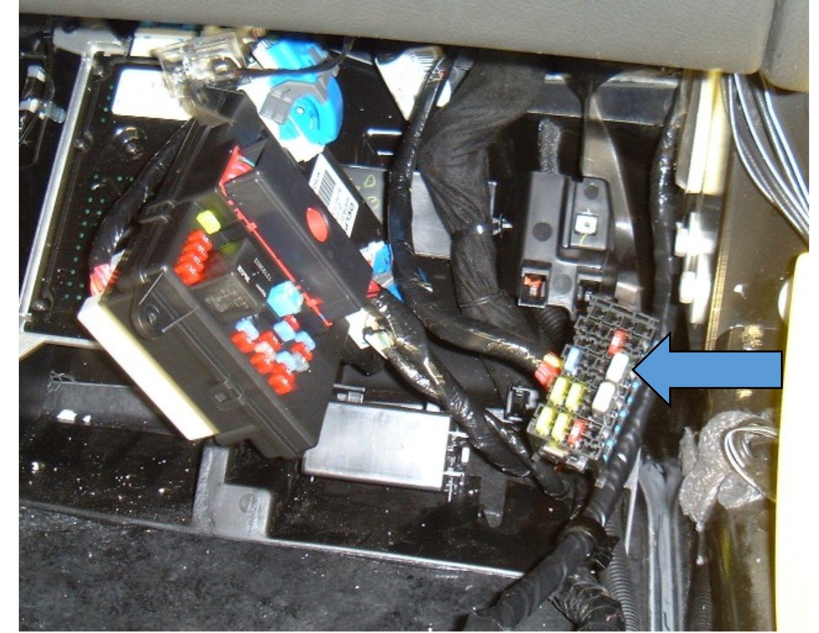
The blue arrow in the above photo shows the Power Seat circuit breaker
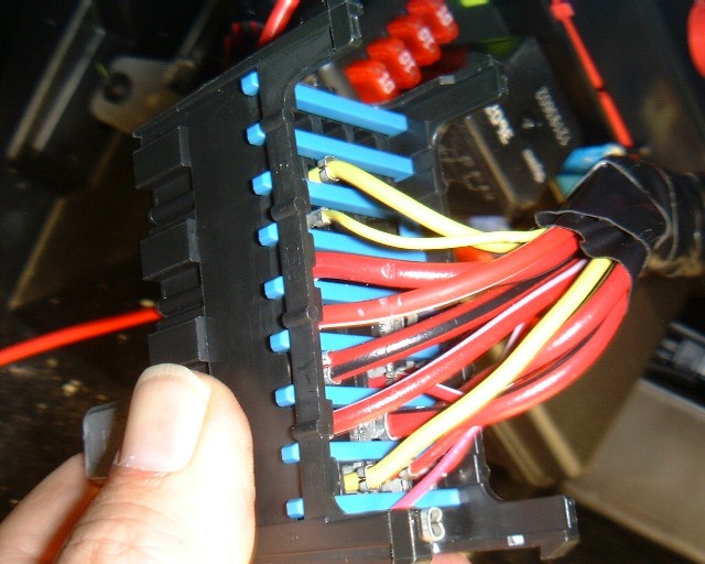
Pull out the circuit breaker panel and look at the back side of it:
Updated 11/15/22 to clarify
CREATING the D3 SPLICE:
Pull the 30 amp breaker for the Power Seats out. This will remove power from the Red/White wire to the Power Seats so you can splice into it safely. See the two small yellow wires? Just below them is the Red/Black power feed to the circuit breaker (always hot). You can't see the black stripe in the photo - it looks red, but this is the power feed to the circuit breaker. With the breaker pulled, the Red/White wire just below it is now dead. Note that the white stripe is barely visible. Now that it is dead, strip some insulation from the Red/White wire a couple of inches back of the panel (you might want to remove some of the tape to make the wire more accessible) and solder on a new #12 wire, thereby creating a feed for the passenger seat. This soldered splice is the D3 splice shown in the original schematic. This wire will now be the missing wire shown in the schematic earlier. Tape up the connection well, then feed the wire in back of the panel, then along the sill plate with the harness you already modified.
Reinstall the circuit breaker panel and the fuse block, but leave off the plastic cover until you later reinstall the 30 amp circuit breaker. Do not install it now, because the other end of your new wire will be hot!
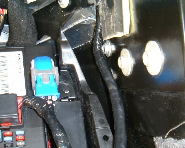
Route the wire along the sill, then reinstall the carpet. Here's what it will look like:
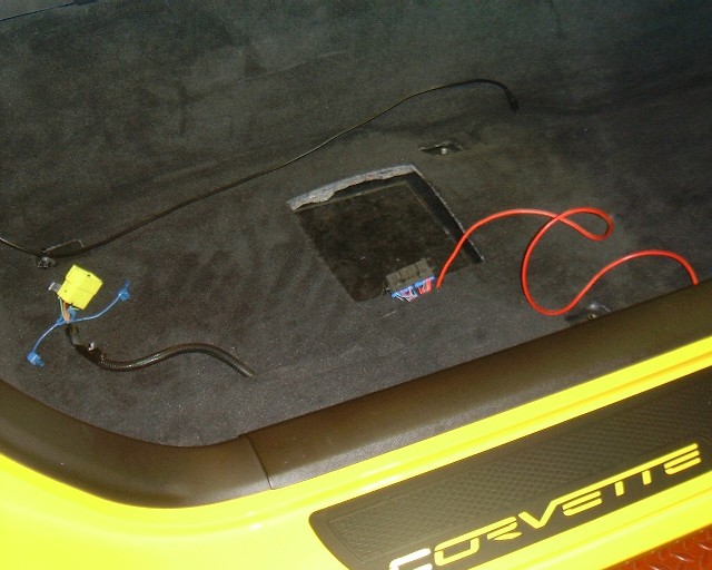
By the way, the yellow connector on the left is for the seat air bag. Before you disconnect this connector (at the beginning of this project), pull the 10 amp fuse in the Fuse Block for the Air Bag. Leave it out until you reconnect the seats.
Here's a closup of the seat connector and the new power feed wire:
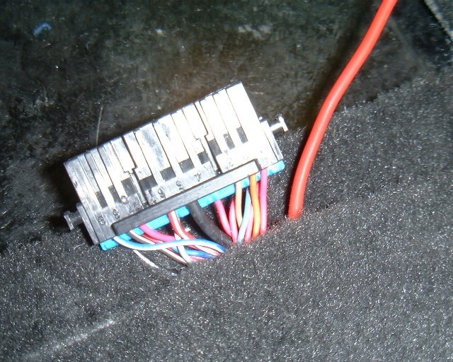
With the help of Paul Pearson (Corvette forum member talon90), I found the terminal I need for this seat connector (C382, Description 18-Way M GT 150 280 Mixed Series BK). The Delphi part number is 15304712. Here's what the terminals look like:
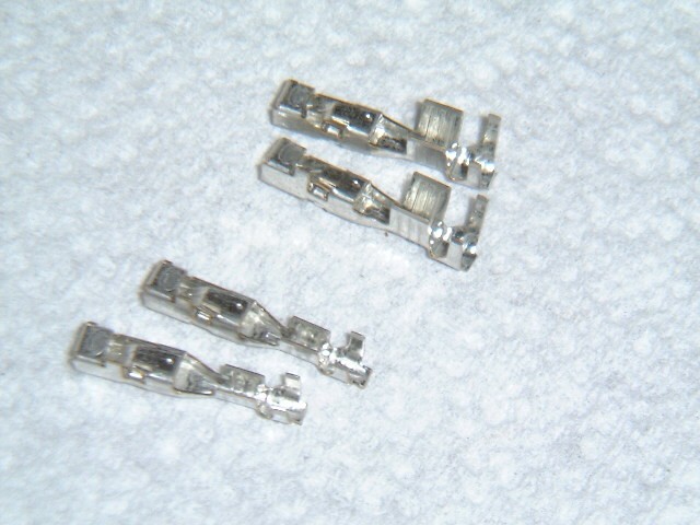
Bob Wendorff, the expert parts man at
Fichtner Chevrolet (forum dealer) sent these to me. The ones on the left
are part number 15304711.
On the right are part number 15304713. The difference is the size of the
wire that the terminal will accommodate.
I used the larger ones because it fit my #12 wire better.
Check with mouser.com to buy the terminals. Just search for 15304713.
If you have a professional crimp tool, you can crimp these terminals to the wire.
Here's the power wire with the new terminal soldered on:
Here's the power wire inserted in the connector:
To insert the terminal, you must first
pull out the blue terminal retainer
(called a TPA for Terminal Position Assurance).
This retainer prevents the terminals from pulling out of the connector.
Now the connector is just like the OEM LT3 connector with the power wire.
OK, it was a big job (it would be easier the second time around), but now the LT3 motorized seat will fit in place and work perfectly. The drivers seat will also fit in just fine, since the Z06 seat is the same as the LT3 seat without the lumbar support module. The wiring is the same. If you change seats, there is one issue to be aware of. If you have memory seats (Z06 2LZ option and LT3), the memory module in the new seat may not be recognized by the Body Control Module because you have changed it out. I found my telescoping wheel would not work and some of the memory functions did not work properly. This could probably be fixed OK if you have the GM Scan Tool and can reset the modules. But I decided to just swap the memory module and use my original one. It can be removed fairly easily from under the drivers seat if you clip some cable ties and unclip the memory module after you unplug the three connectors. Then just reinstall the original module in the new seat. Once I did that, everything works great.
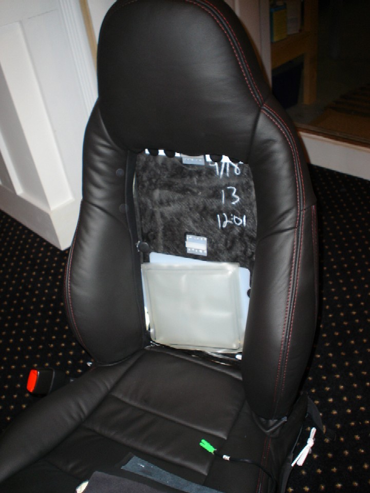
Here's a photo of the new passenger seat:
and the new drivers seat:
Both have full power and lumbar support. I think we are going to like these seats a lot better on our long road trips.
For those of you who don't feel you want to tackle a project this big, here are some thoughts on some options you might consider:
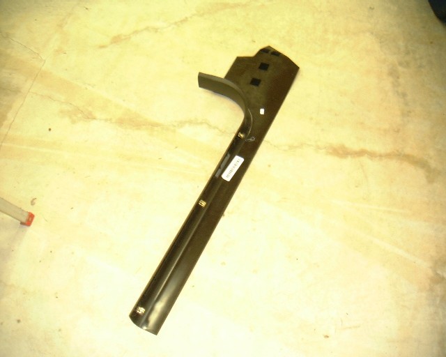
1. If you just want to add lumbar support to the drivers seat, you only need a couple of parts. First you will need to obtain the lumbar pump and bladders. This is a one-piece package available from GM. The bladders fit behind the side bolsters and the seat back insert of the seat back. You will need to disassemble the seat covers to insert them. This isn't particularly easy on your first go-around, but it can be done. The pump is cable-tied to the seat structure underneath, and the plug is already there in the drivers side seat harness. You will also need the lumbar switch assembly, which is part of the bezel shown in the picture above. This bezel (and switch) simply replaces the Z06 bezel that does not have the lumbar support. The switch has a connector that plugs in the seat harness. So other than having to take apart the seat covers, this is a pretty easy installation.
2. If you want to add lumbar support to the manual passenger seat, you won't need to move the Onstar module and you won't need the new power wire (since there are no motors to power). So that is much easier. However, in addition to the lumbar pump and bladders, and the new switch and bezel, you will also need a new seat wiring harness. The Z06 wiring harness does not have the plugs for the pump or switch. And you will also need the metal plate to which the new switch/bezel attaches (unseen in the photo because it is behind the bezel). Also, this bezel has an oblong cutout in it for the power seat switch - without the switch, you will see this hole.
If you are really clever, you can do without the switches and hardwire the lumbar module into the existing harness. Then mount your own switches somewhere else. Electrically, this is pretty simply, but you still have to remove the seat and take the covers off, then figure out where to connect up your components.
Anyway, this was a lot of work, but now we know it can be done. I'm getting pretty good at taking Corvette seats apart, so at least I learned something. I'm happy to answer any questions if there are other curious Z06 owners who don't like their seats.
Just email me at ray@kawal.net
MORE PHOTOS BELOW
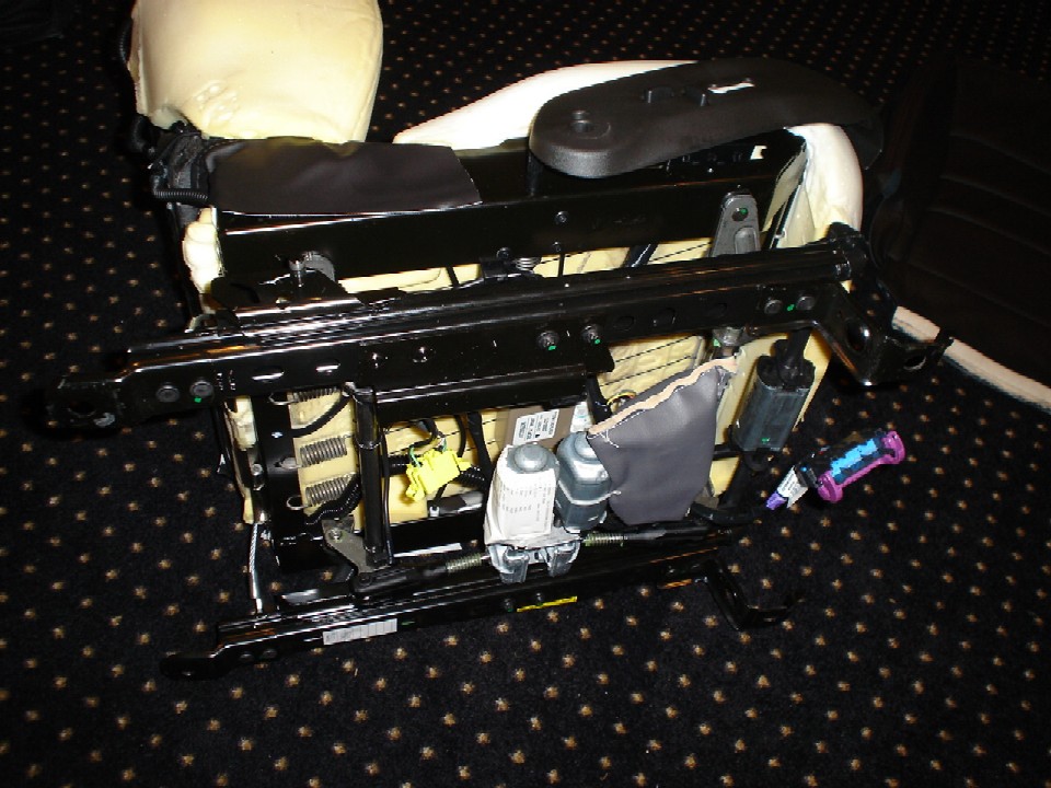
Here's a photo of the bottom of the new passenger seat:
The lumbar pump is in the black bag.
It is just strapped to the motor in the back and the seat support bar in front.
Here are some more seat photos from another Corvette Forum member, Bill Clements
Here's a seat with the covers removed.
The center lumbar bladder is shown on the seat back.
Here is a power seat frame with the lumbar module:
These are the plastic fasteners that hold the seat covers in place:
Seat with center lumbar bladder. The side bladders are behind the side bolsters.
Bezel plate to hold the power seat switch in place and support the plastic bezel cover:
Bezel with lumbar switches:
For those of you who may find the driver's side electrical information useful,
here is the driver's side main seat connector C375:
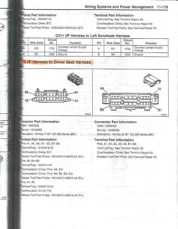
and the pinouts:
With the 2LZ package, you will have a memory driver's seat.
There is a second connector C379:
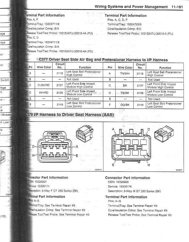
and the pinouts:

Here are the schematic wiring diagrams for the memory module:

