C6 Corvette Navigation Modification
(updated 4/9/15)
Click here for
main website
This modification allows the driver or
passenger to enter navigation information such as destination or other points of
interest anytime, whether or not the vehicle is moving.
There are a few different ways to do this:
(Click on each Alternative to go
directly there, but start with Alternative 1 if you are not yet familiar with
this modification. )
Alternative
1: Splice a simple switch into the Navigation Wiring Harness (cost less
than $5)
Alternative
2: Connect the new switch into the wiring harness using Delphi connectors
and terminals, which allows the installation without cutting into the factory
wiring harness.
Alternative
3: Connect the new switch using a custom adapter harness this is simply
plugged in.
 Alternative
4: Same as Alternative 3, but adding an Auxiliary Input jack for
connection of music devices.
Alternative
4: Same as Alternative 3, but adding an Auxiliary Input jack for
connection of music devices.
Alternative 5: Install Ben Stanley's Sunset Orange Creations Navigation Commander.
Alternative 1:
Splice a simple switch into the Navigation
Wiring Harness (cost less than $5)
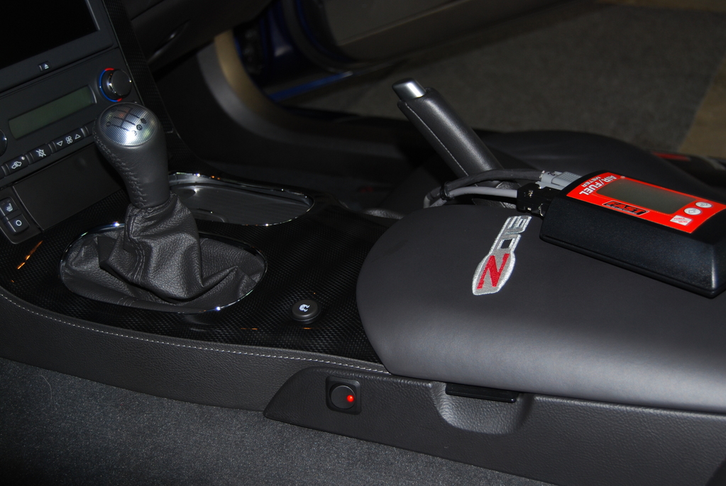
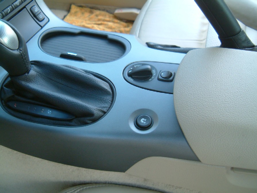
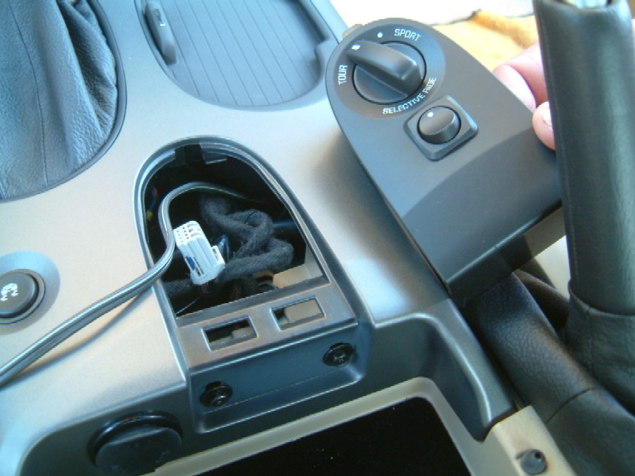
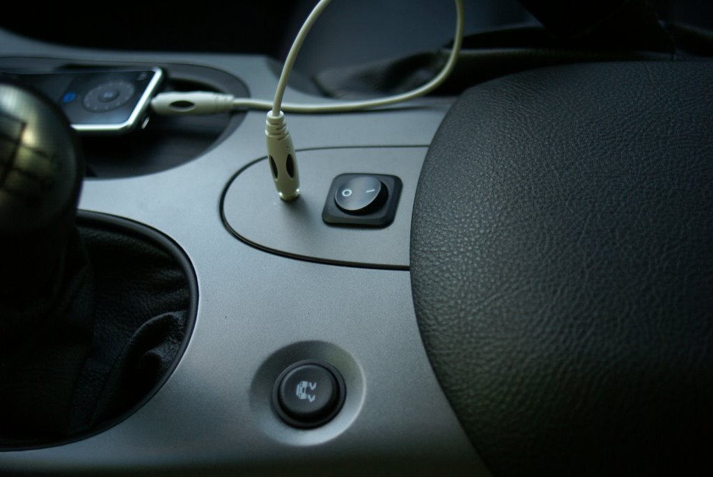
These first photos are from the
installation in my Z06. See the switch next to the ash tray?
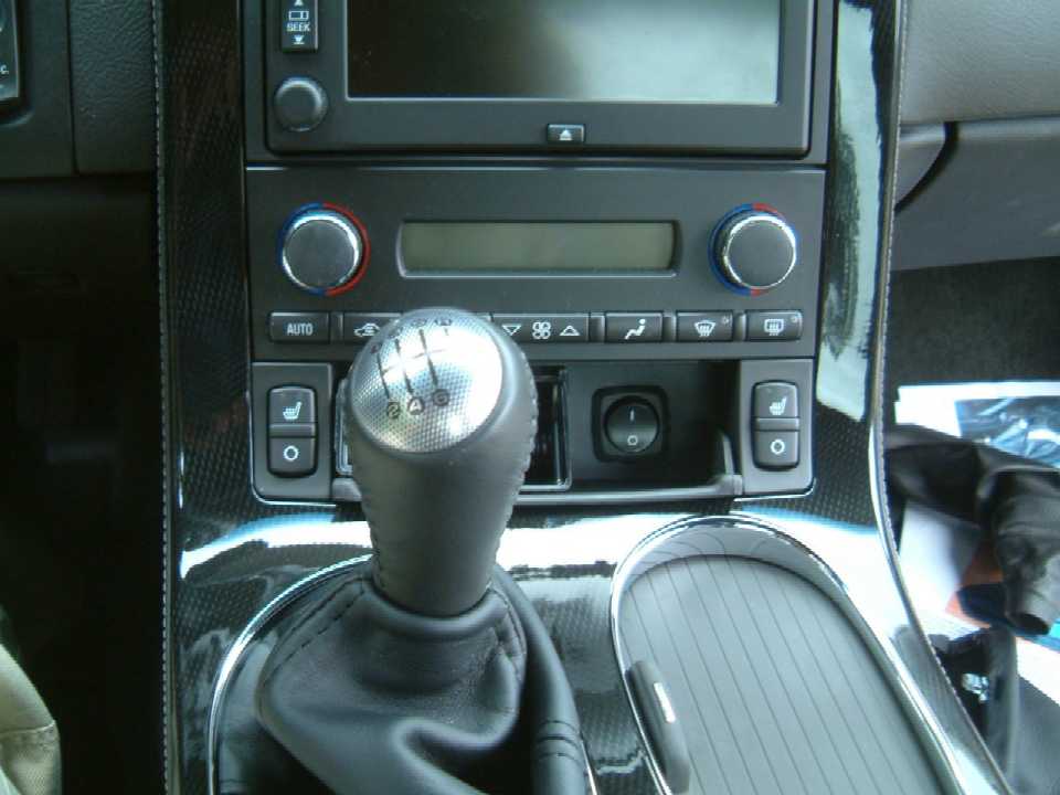
Here's the end result - it's only a $3 switch from Radio Shack.
In the switch position shown, the Navigation unit works the same as straight from
the factory.
If you switch to the other position, you can enter destinations into the nav
unit at any speed.
Once entered, you must switch back to get the nav unit to track your
position.
************************************
Depending on your year and model, there
are other possible locations for the "Nav Switch":
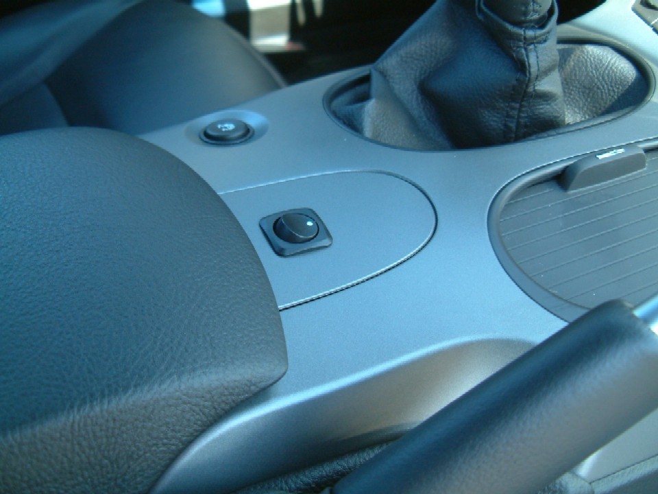
The photo above was taken when I first installed the switch on my '07 Z06.
I later installed the newer style '08 console.
Photos further below are in my buddy's
LT3 coupe with automatic and Selective Ride Control.
OK, here's the discussion:
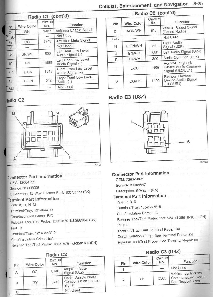
The Denso manufactured nav unit has a number of connectors plugged into the
back of the unit.
Connector C2, Pin D, is the signal from the Vehicle Speed Sensor. This
signal is used to not only indicate movement of the vehicle on the nav
maps,
but it also allows the nav unit to remove the various destination displays
once the vehicle is moving about 3-4 mph.
This feature is installed for safety reasons so the driver can't be fiddling
with destinations while he or she is driving.
But if there is a passenger, why not let him or her input destinations while
you are traveling?
Removing the speed sensor signal tricks the nav unit into thinking you are
stopped, so you can input destinations at any speed.
Removal of this signal also prevents the nav unit from tracking, so you must
put the signal back after you enter your new destination.
So the simple solution is to cut the wire to the 817 circuit and splice in a
switch.
Follow along to see how to do it.
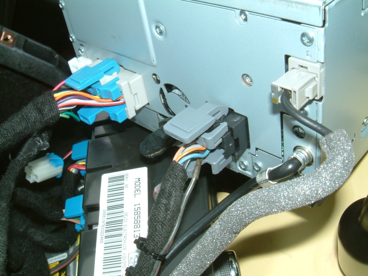
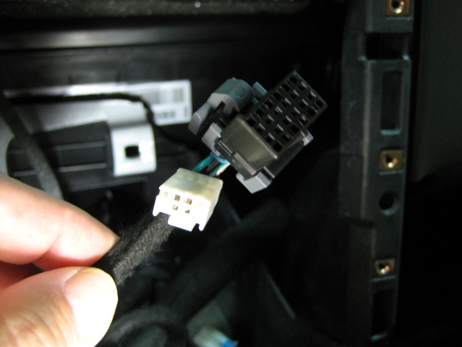
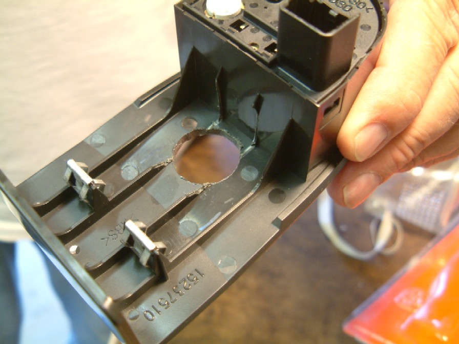
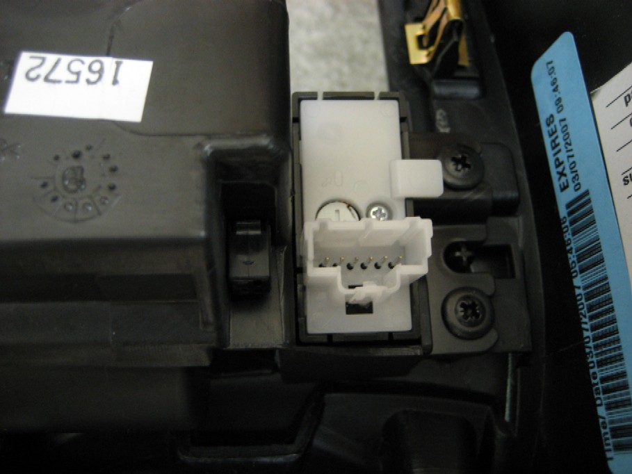
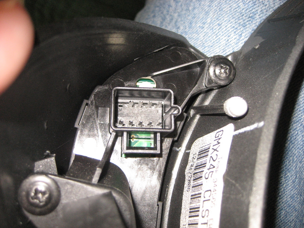
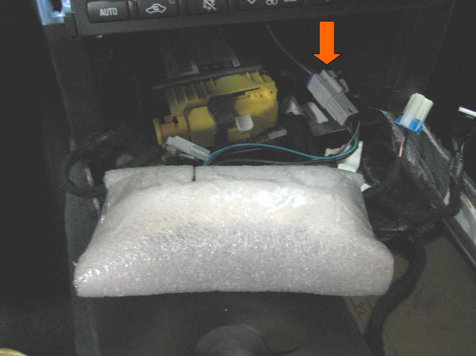
Here's the back of the nav unit.
The plug on the right (Connector C2) is the one we want to get to.
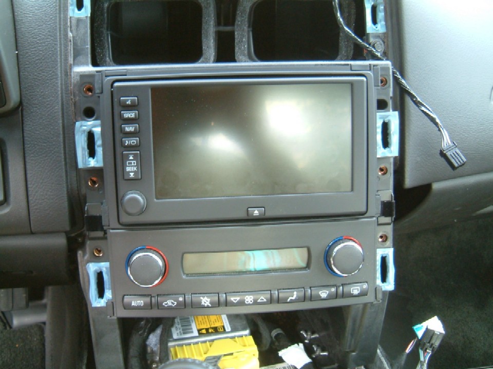
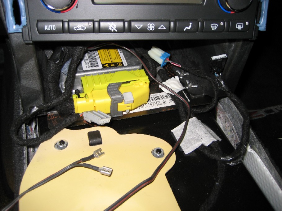
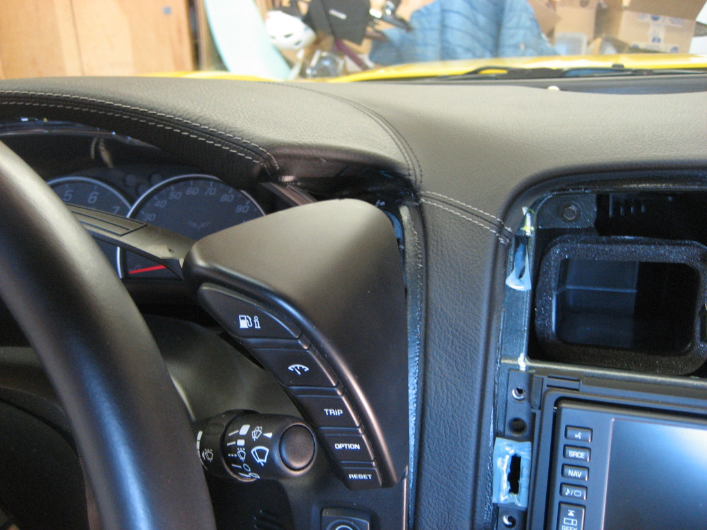
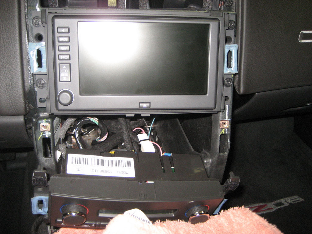
Here is the nav unit and the heating controls sitting in place after the
trim panel is removed.
(All six screws holding them in place are removed.)
To get to this stage, you'll need a couple of Torx screwdrivers and a 7mm nutdriver.
1. Open your console cover (lid) and remove the cover with a T15 Torx driver (4
small screws).
2. Pull down the emergency brake boot in the front and it will
reveal two 7mm screws holding the side trim plate on. Remove the two
screws and pull down the side trim plate away from the dashboard.
2. Lift up on the back of the small trim plate (tombstone shaped) where the switch will be
mounted (see 1st photo).
This plate is held in with two snap fasteners, so just lift firmly at the
rear and it will come loose.
(Note that for the 2008 consoles, there is no tombstone plate.)
3. Push down on the leather shifter cover to expose the T-25 Torx screw
holding the shift knob in place.
Then remove the knob.
(Note this is not necessary for automatic transmission cars.)
4. Remove the two screws at the rear of the trim panel inside the
console using a 7 mm nut driver.
5. Pull up firmly on the trim panel at the rear and it will come
loose. Notice in the photo above
that there are also snap fasteners at the front (all six are shown in the
blue tape).
As you lift the panel, these front fasteners will pop out as you lift.
6. Once loose, you will need to disconnect the plugs for the seat
heaters (if you have them), the cigar lighter, the traction control switch, and the hazard warning switch.
This is necessary to get the trim panel out of the way.
(See photos near the end for some helpful hints to
remove these connectors.)
I found it easiest to move the shifter into 2nd gear so it will clear the
trim panel easiest.
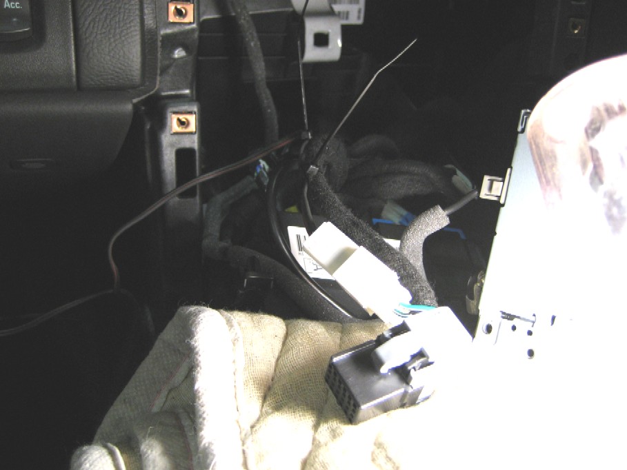
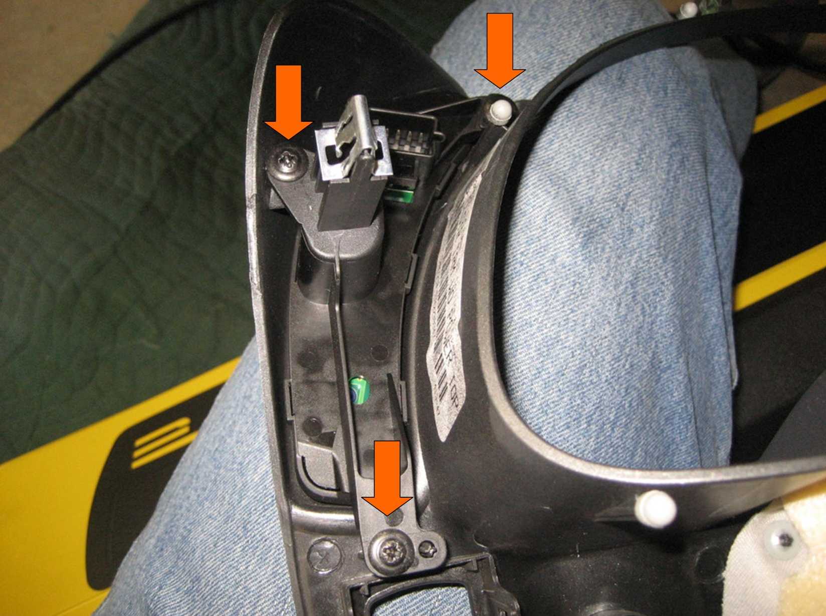
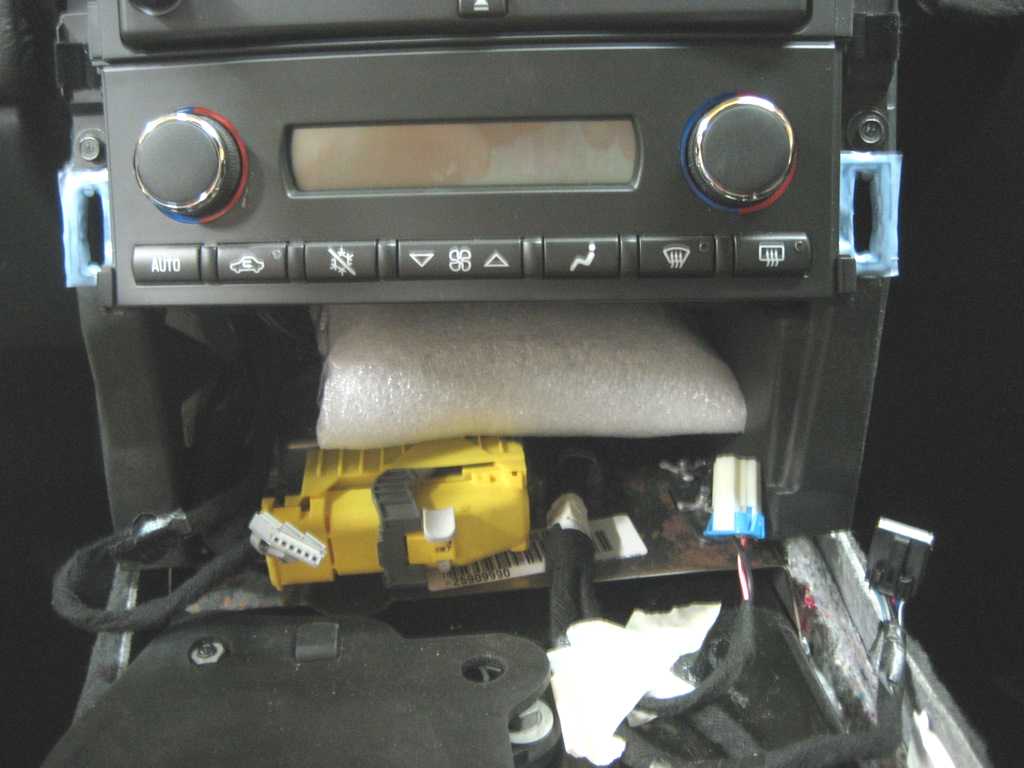
7. Lay the trim panel on the passenger seat out of the way. Once
done, you will see what is in the photo above.
8. Remove the two screws holding the heater controls in place, pull it
out a bit, and lay it down.
9. Remove the four screws holding the nav unit in place, and pull it
out enough to get to the rear plugs.
(Find some padding to lay on top of the shifter know
to prevent scratching the face of the nav unit.)
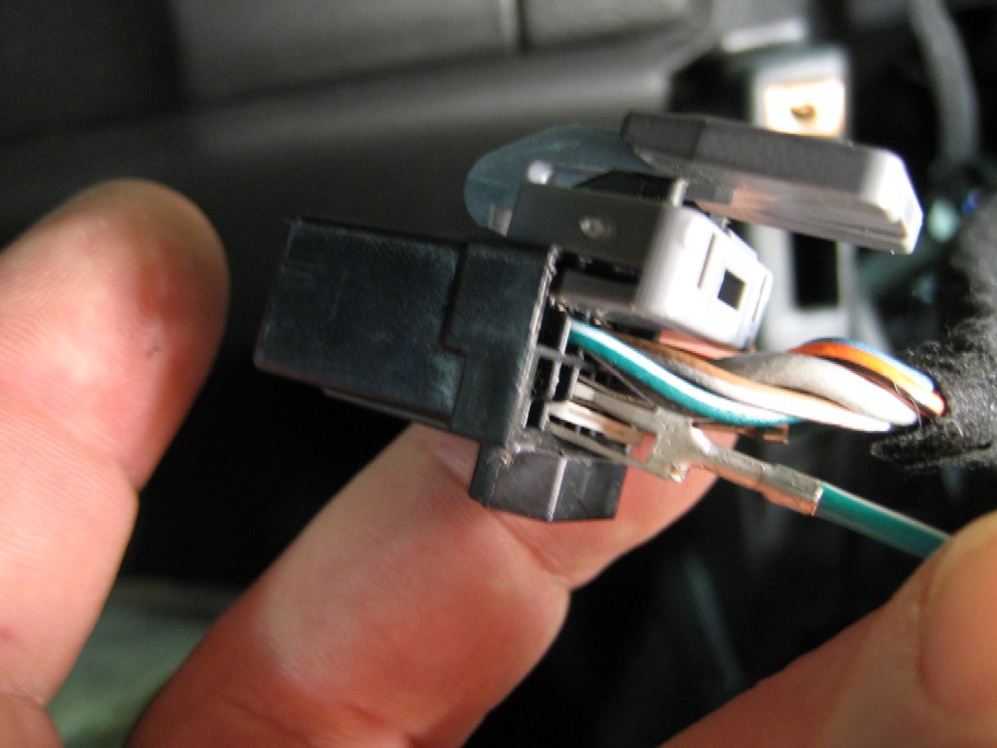
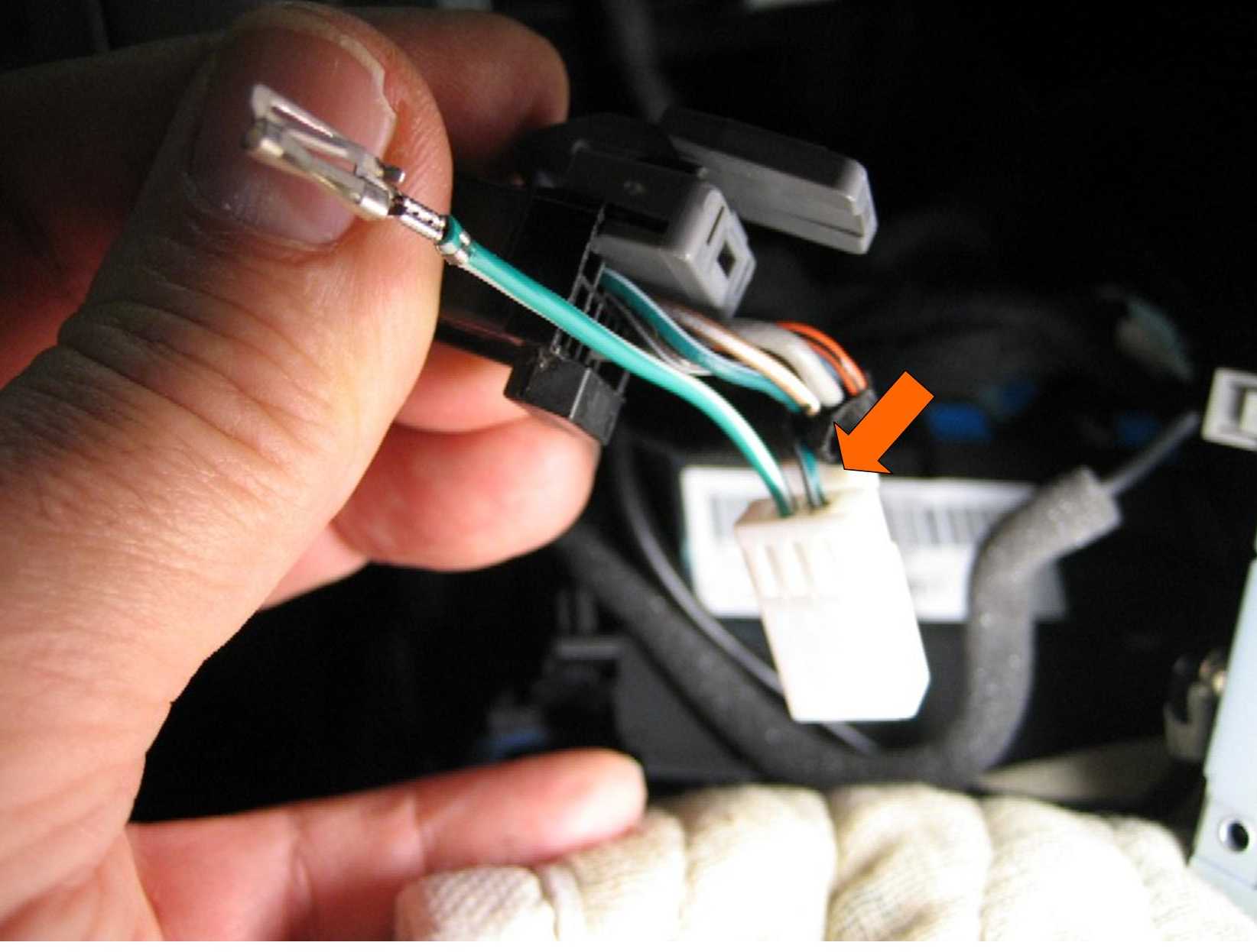
10. Press down on the Connector C2 lock and pull it out of the nav
unit.
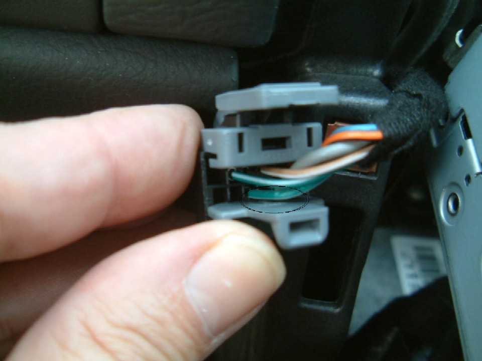
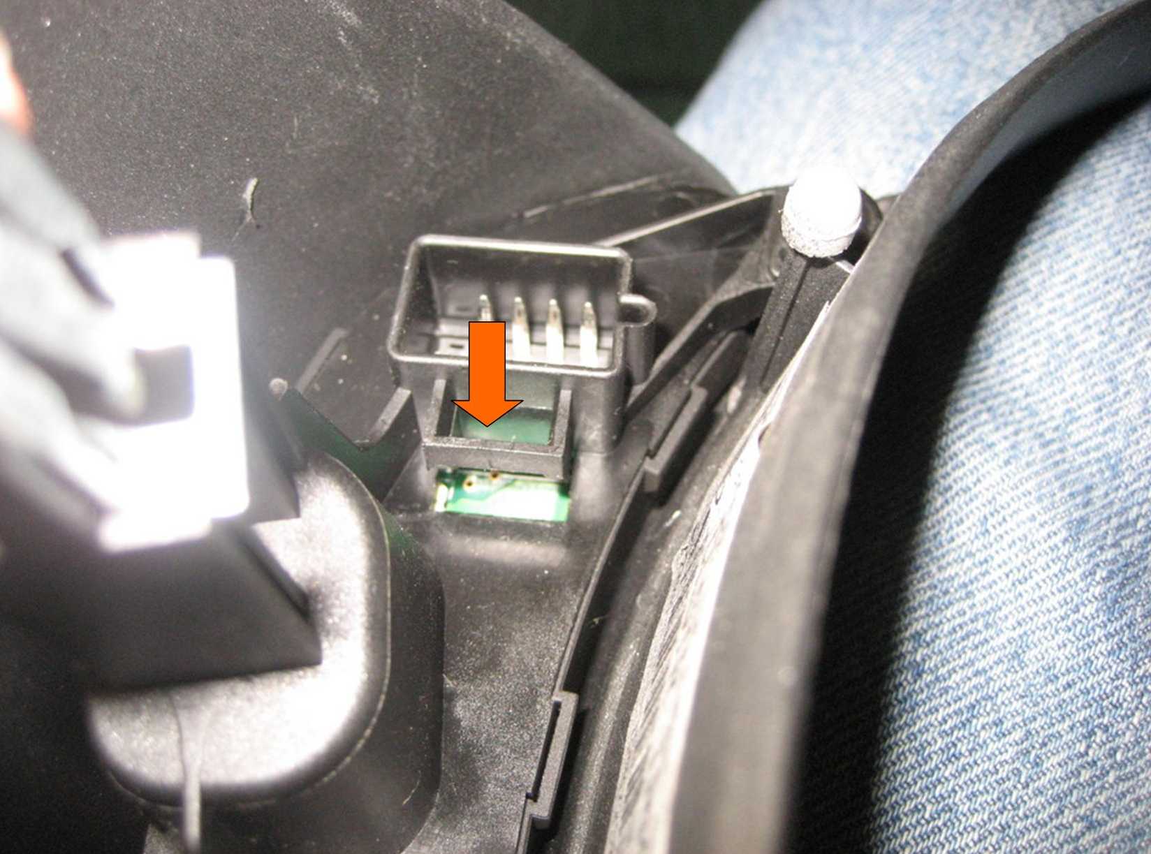
Here's a closeup view of the back of Connector C2.
The green/white wire on the bottom (Pin D) is the one we want to cut.
Note that there is another green/white wire in Pin H - do not mistake this
wire for the correct one.
Remove the gray wire keeper at the bottom of the plug to provide easier
access to the wire we want.
(This "wire keeper" is called a TPA for "terminal position
assurance". It MUST be removed before a terminal can be removed.)
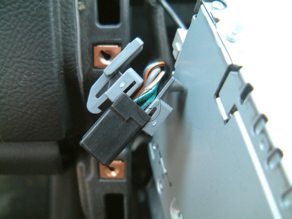
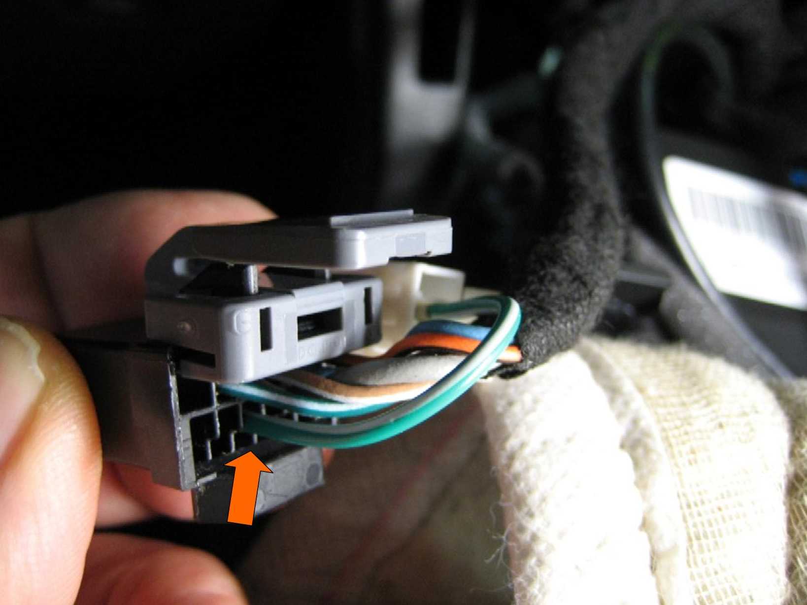
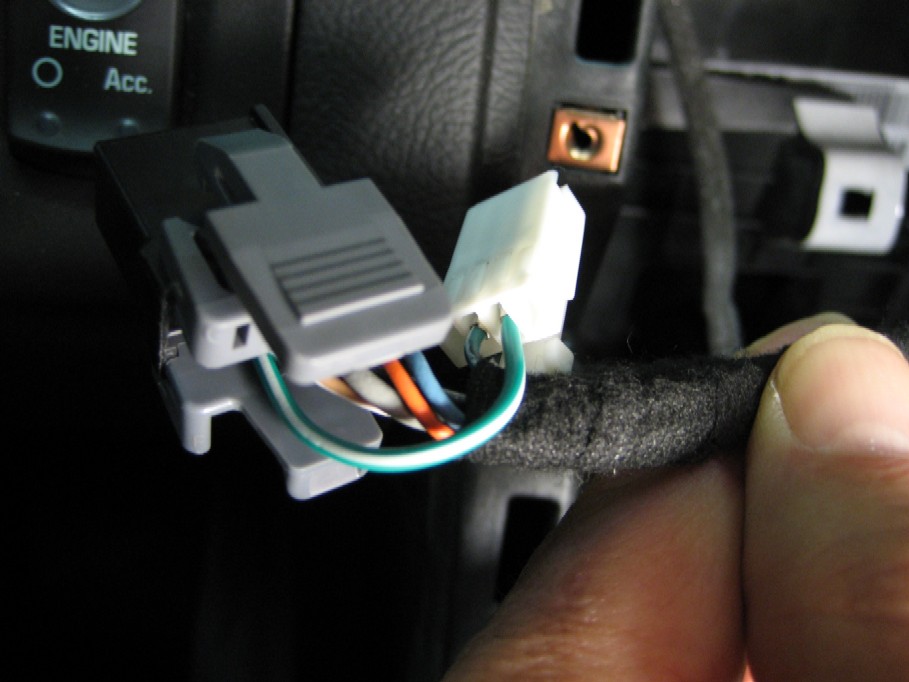
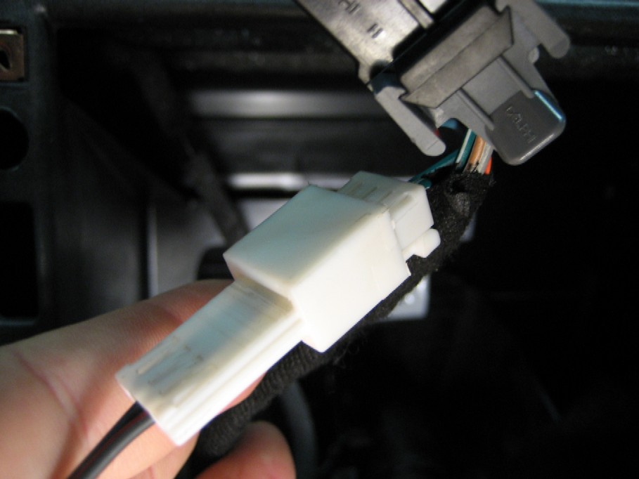
Here's another closeup view of the C2 connector. The green/white wire
shown is the one we want to cut.
OK, at this point you must decide whether
you want to cut this wire or obtain an adapter harness that will allow the
installation of the switch without cutting any wires.
Read on, then decide.
Here is the first alternative of cutting the wire:
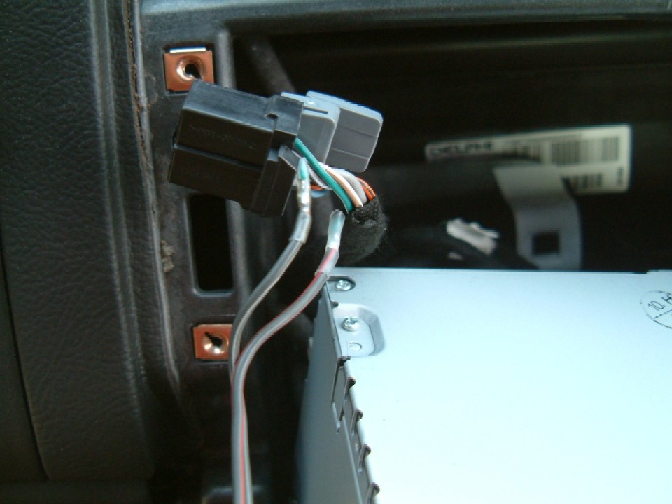
Obtain some two conductor wire (about 3' will do) for splicing into the
circuit.
I found some 18 gauge speaker wire I had laying around works very
well.
Cut the green/white wire between the plug and the cloth insulation, then
solder the two new wires to the ends.
Use heat shrink tubing to insulate the connection.
This is the hardest part of the job, because of the care you must take in
splicing the wires.
Install a couple of cable ties to prevent accidentally pulling on the spliced
connections.
Now all of the hard work is done. Reinstall the gray wire keeper on Plug
C2, then plug it back into the nav unit.
Route your new wire under the nav unit and reinstall the nav unit with the four
screws.
Reinstall the heater control with the two screws.
Route the new wire along the console to where the new switch will be.
Reinstall the trim panel after reconnecting the plugs you previously removed.
Reinstall the shifter knob.
Any small switch will do, but this one from Radio Shack worked
great.
It mounts in a 3/4" hole drilled in the plastic trim
plate.
Simply connect the loose ends of the new wire to the switch
using push connectors and snap the trim plate back in place.
Install the console cover and you're done.
Here's a hint:
When reinstalling the Nav
Unit and the heater controls, before tightening the screws, push up the heater
controls as far as possible.
There is a bit of play and I found my ashtray would hit (barely) the heater
controls, until I raised it ever so slightly.
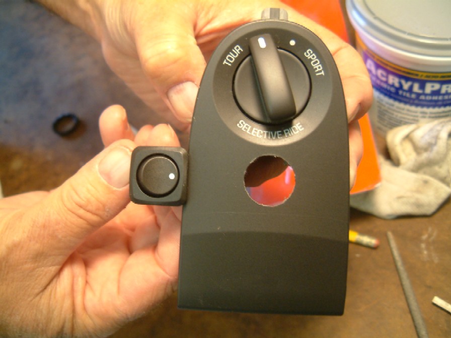
The shot above was taken before I installed a new 2008
console in my Z06.
The '08 console does not have the small
"tombstone" plate for the F55
suspension where I mounted the switch shown in the previous photos.
Rather than drill a hole in my new console for the old
switch, I decided to remove the cigarette lighter and use that location for a
new switch.*
The new switch I also found at Radio Shack, model number
275-730.
Now I have to flip open the ash tray door to use the
switch, but it's pretty easy.
(*see down near the bottom of this page for details on how to
remove the power connector/cigarette lighter)
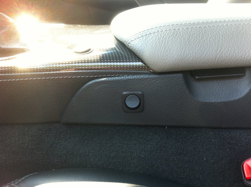
Here's another possible location for the
switch:
Note that this appears to be a lighted
switch, but remember that this circuit does not provide any power for a switch
light.
So you might as well buy a nice looking
unlighted switch for this modification.
Here is forum member Bob Pipkin's
installation:
Here's another installation from Tony Zuaro:
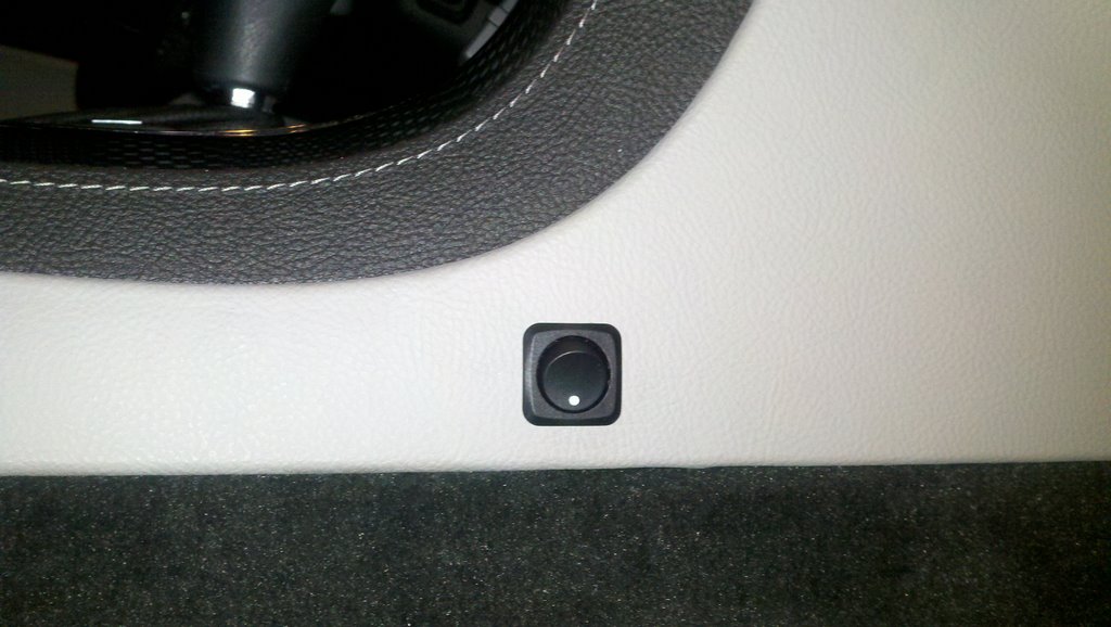
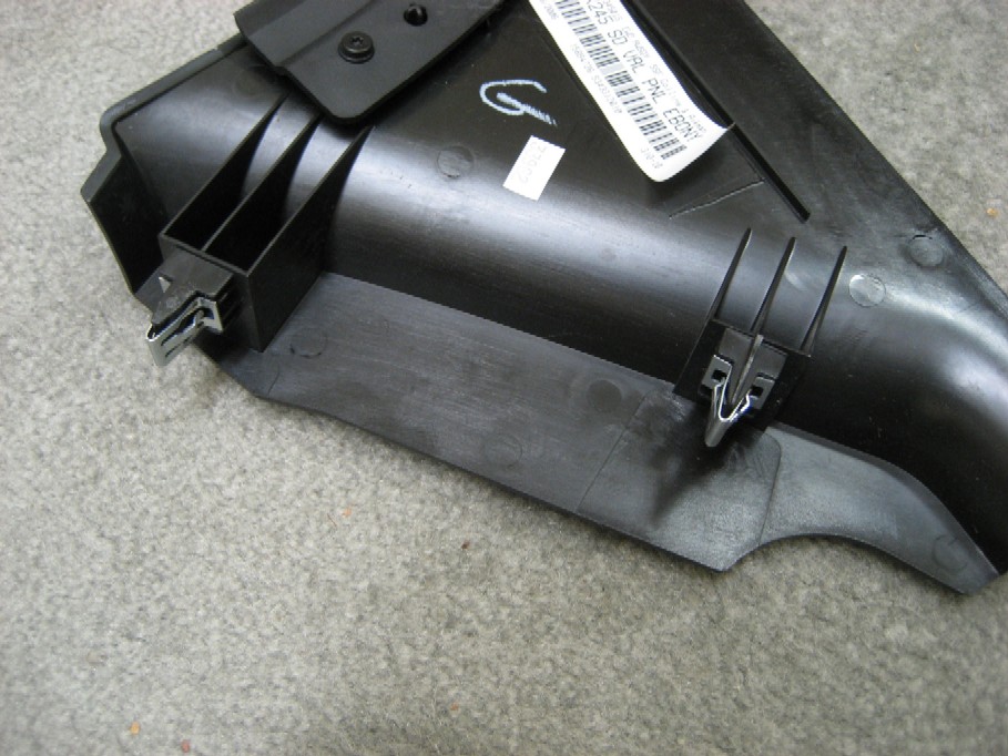
The right side console panel shown above is
easily removable.
OPERATION:
To use the modified nav system, leave the switch in place as
shown, except when you want to enter a new destination.
While you are driving, switch to the other position, which
removes the speed signal from the nav unit.
Your Destination Menu will reappear, and you can input
whatever you want.
Once you select "Guide" and the nav unit
recalculates your route, move the switch to the normal position for tracking.
Now that your frustrations are over, enjoy the nav system as
it should have been designed!!
(Update 6/22/07):
After a 2000 mile trip, the nav mod works great! But
there is one issue to note.
When the switch is in the "mod" position, there is a
limited time you have to input data
before the nav unit resets itself and you lose the Destination
Menu.
Usually, there is sufficient time to input your data, but
occasionally you will have to switch back to "normal" and wait a few
seconds for it to blink.
Then switch back to the "mod" position and continue
entering your data.
If you are waiting for a long "list" of points of
interest, you may have to switch back to "normal", then
"mod", a couple of times.
OK, here's the second
alternative for those of you who don't want to cut into the factory harness or
don't want to do any soldering:
Alternative
2:
(The NAV-1 harness)
Connect the new switch into
the wiring harness using Delphi connectors and terminals, which allows the
installation without cutting into the factory wiring harness.
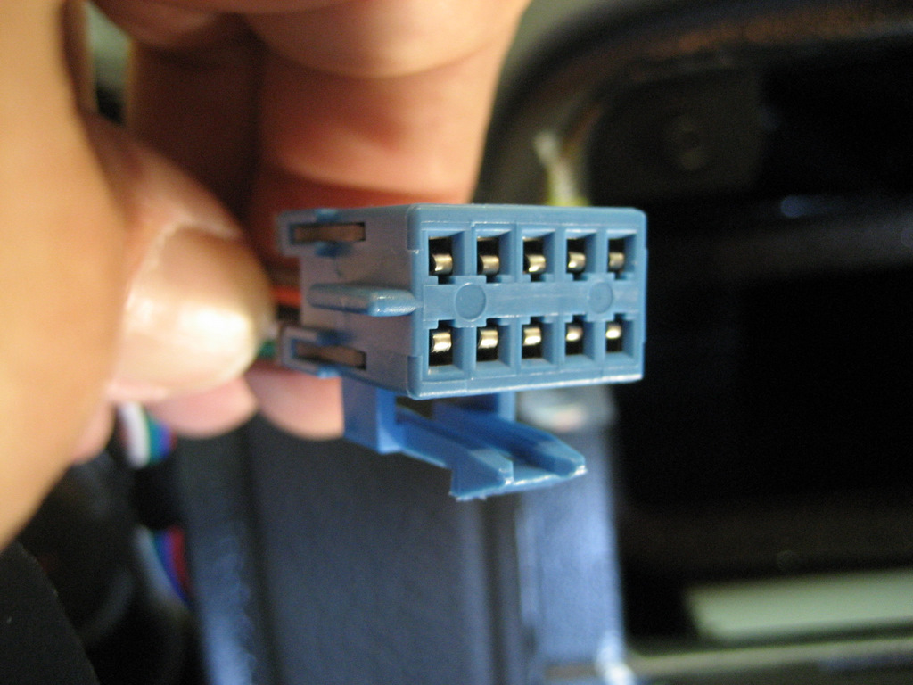
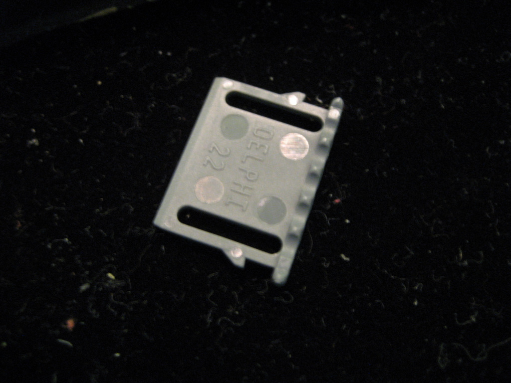
As shown on the page of the Service Manual above, the 12
pin connector is a Delphi 12-way female Micro-Pack 100 connector, part number
12064799.
The female terminals are part number 12146447.
Here's a closeup of the connector with all wires removed:
Note the green/white wire is in position D, the third slot
from the left on the bottom.
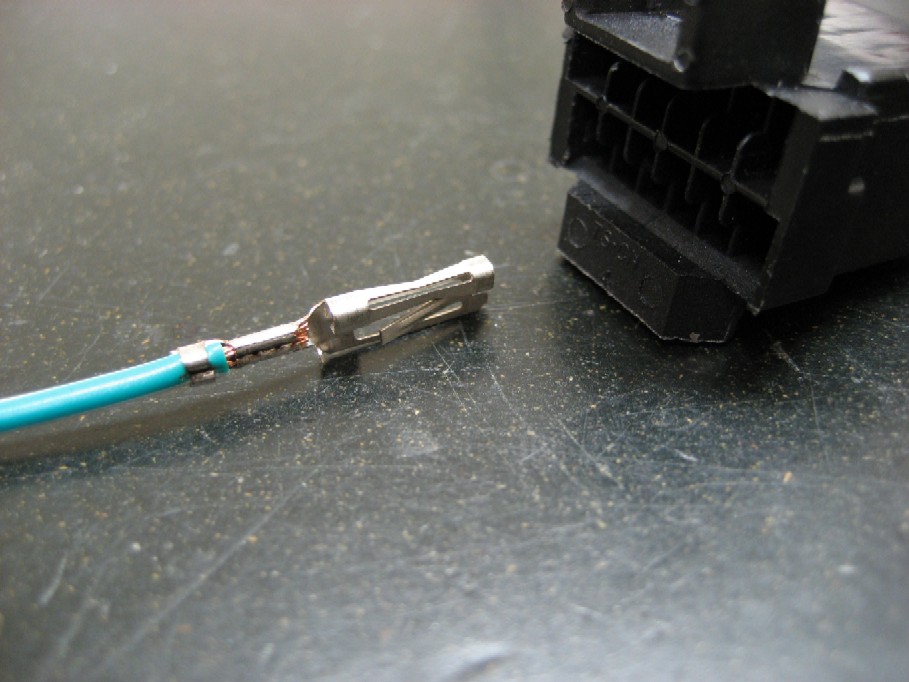
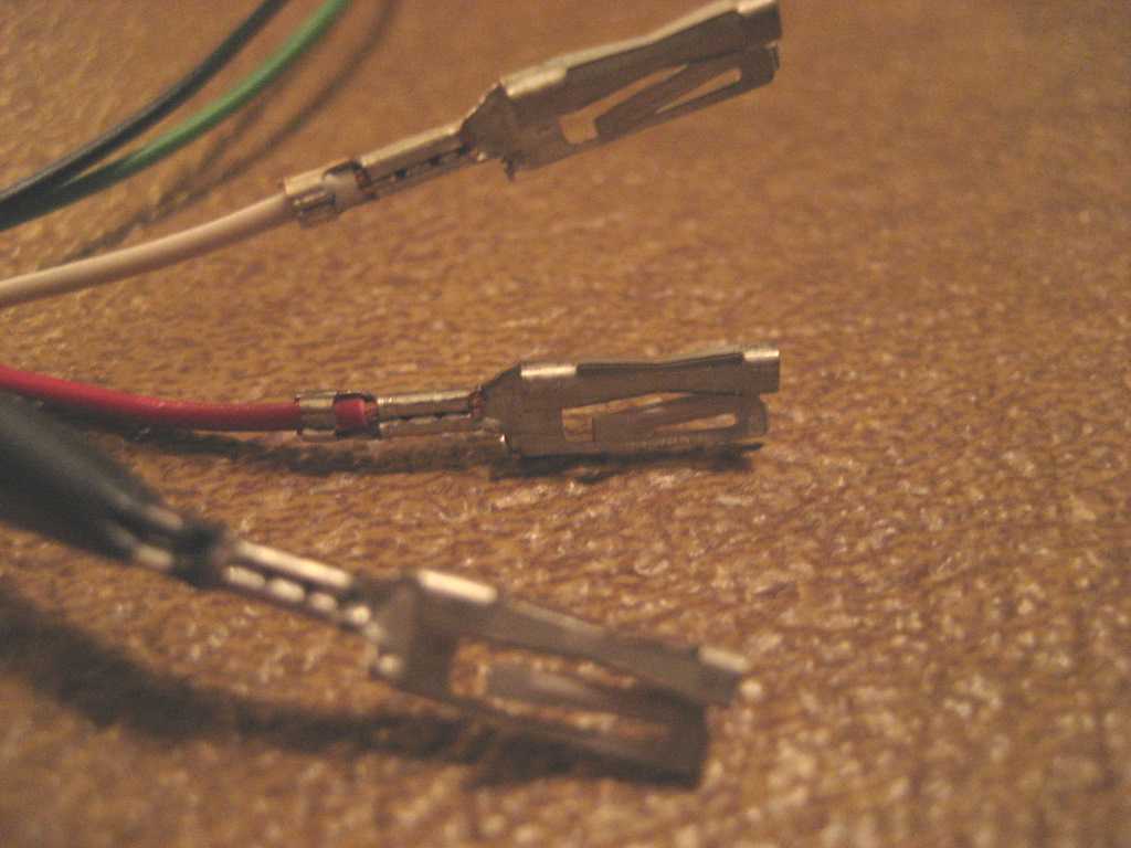
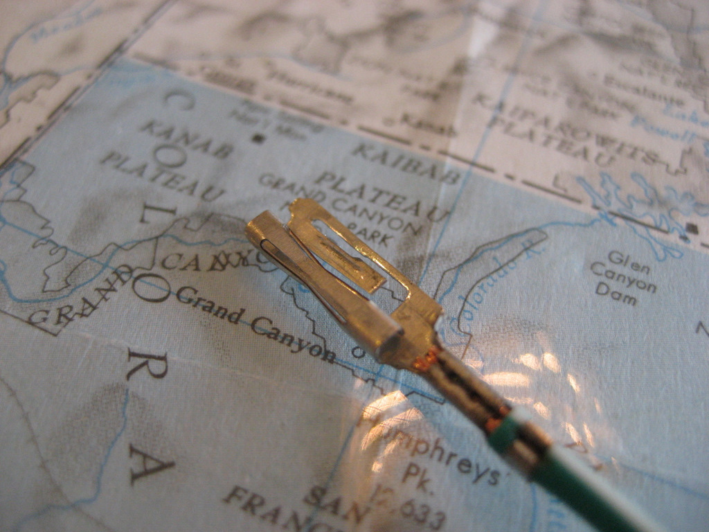
Here's a better closeup of the terminal.
The Delphi Micro-Pack 100 connectors have been used for
years in GM radios.
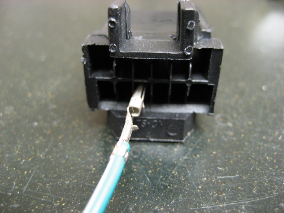
To install a switch in the Pin D (green/white) wire of the
12 pin connector, you must first remove the terminal from the connector.
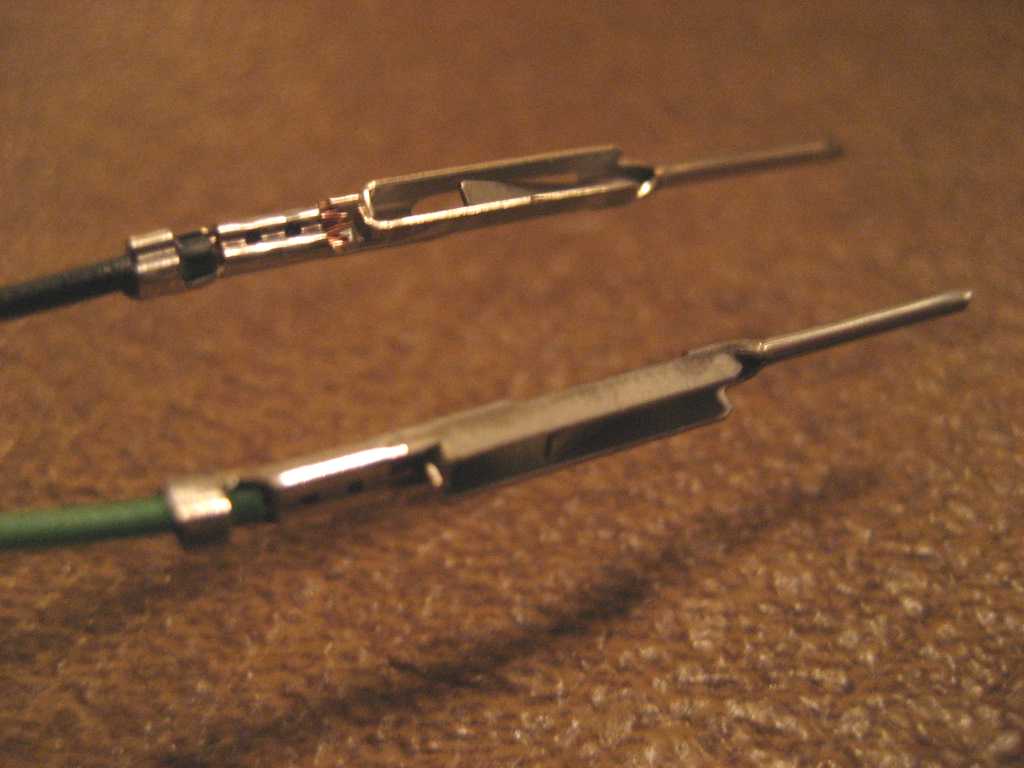
Here's what the terminal looks like up real close:
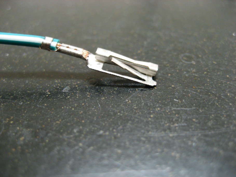
See the locking tab? That needs to be pushed down to
release the terminal.
(Be sure the TPA described above is removed before you
attempt to remove the terminal!)
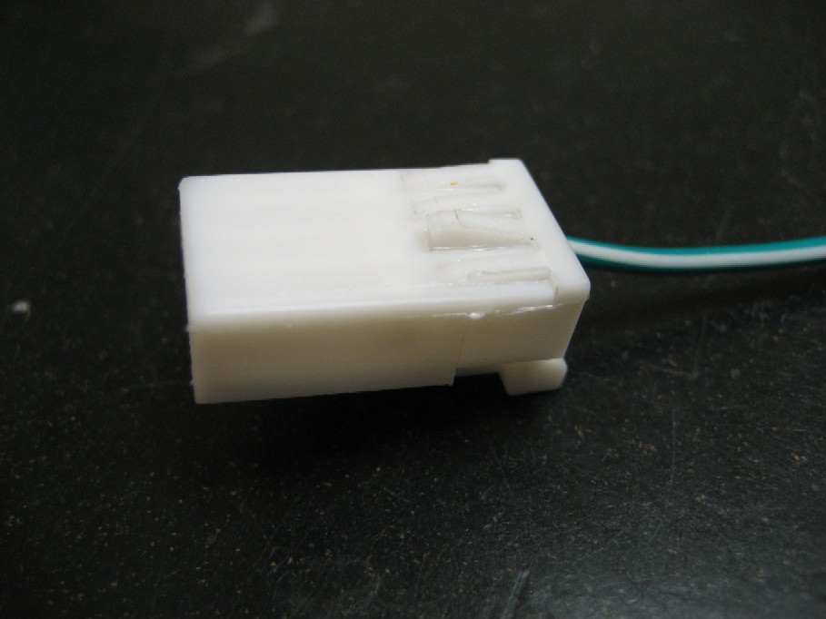
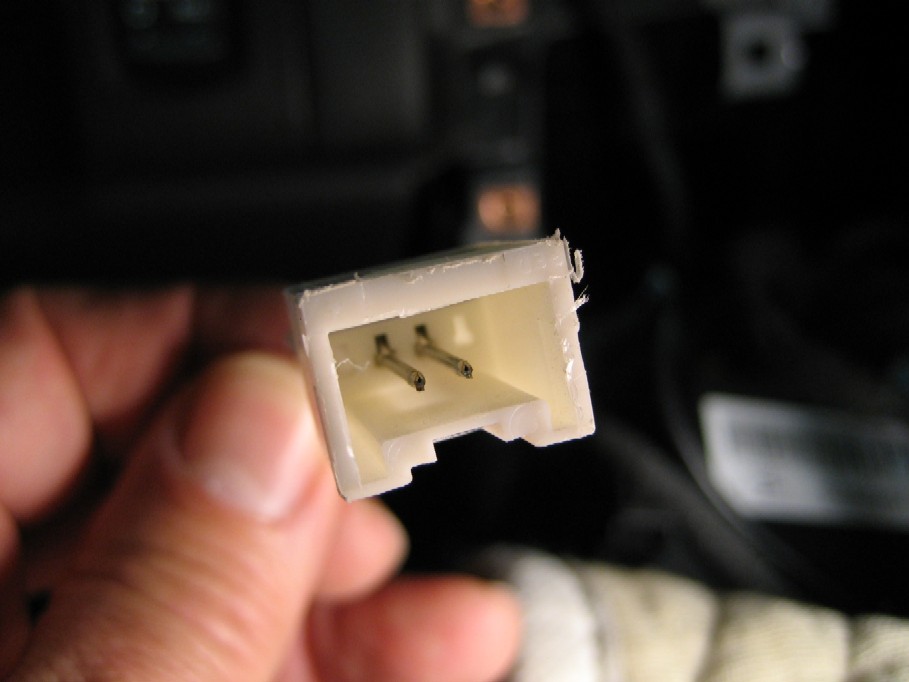
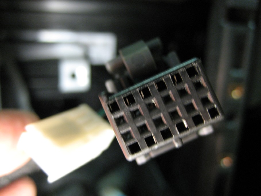
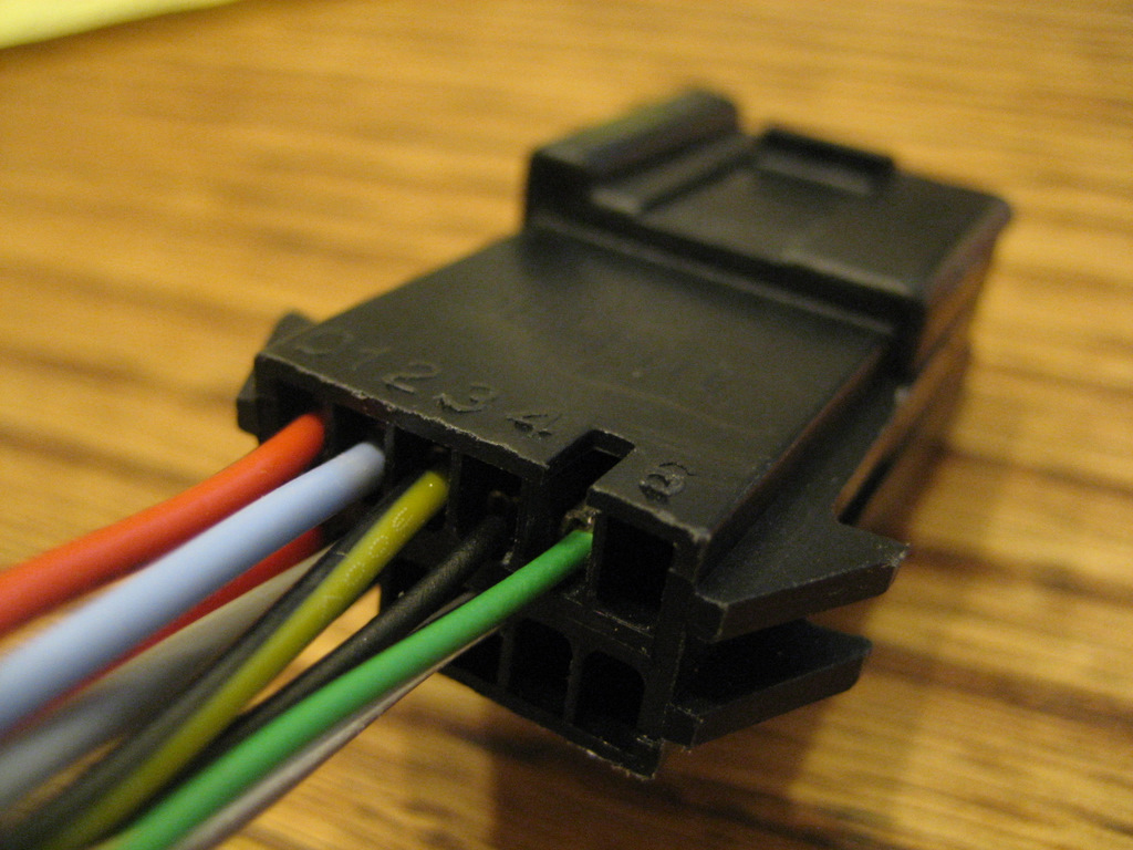
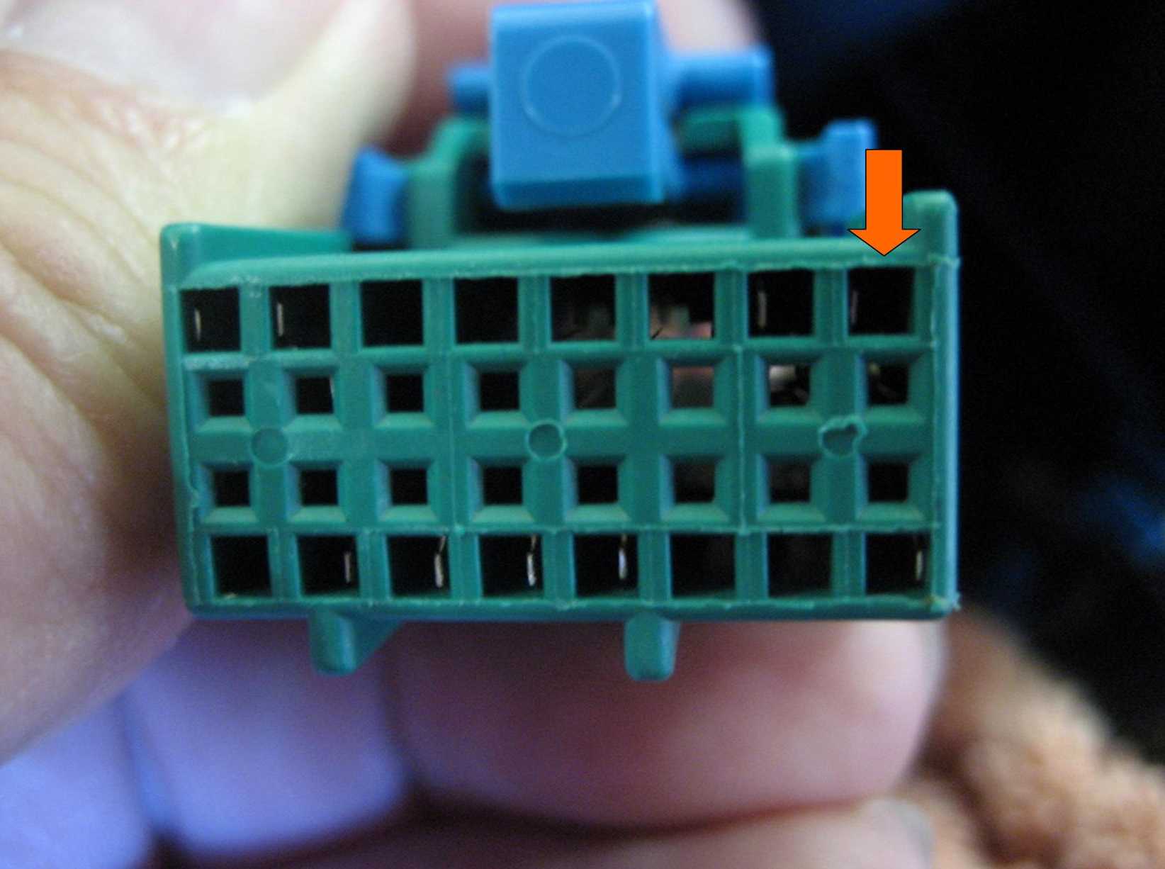
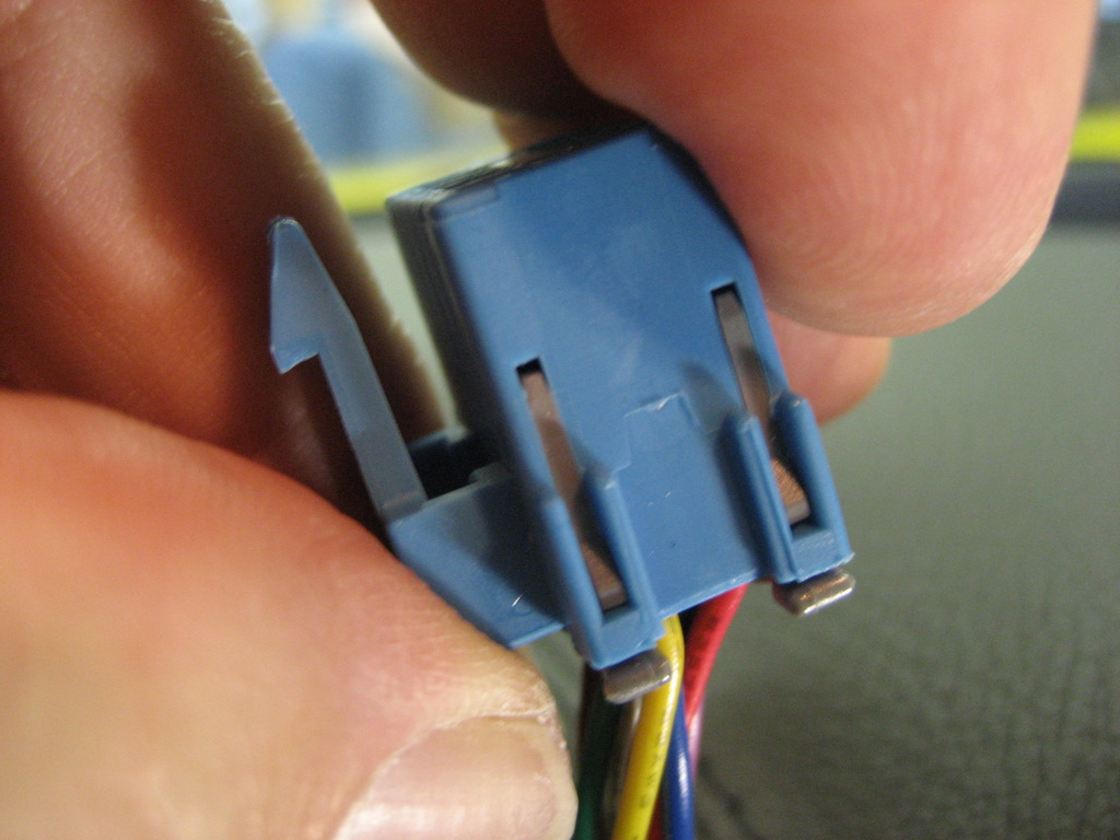
Here's the front of the 12 pin plug
with no terminals installed:
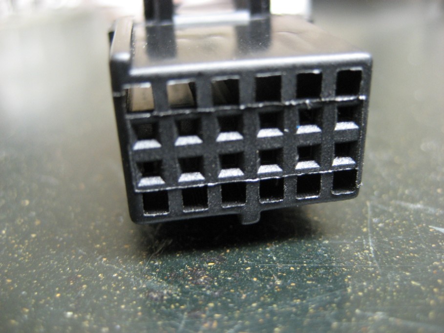
The middle 12 holes are where the terminals make their
electrical connections.
The top and bottom rows are where the locking tabs lock into the connector to
prevent them from coming out.
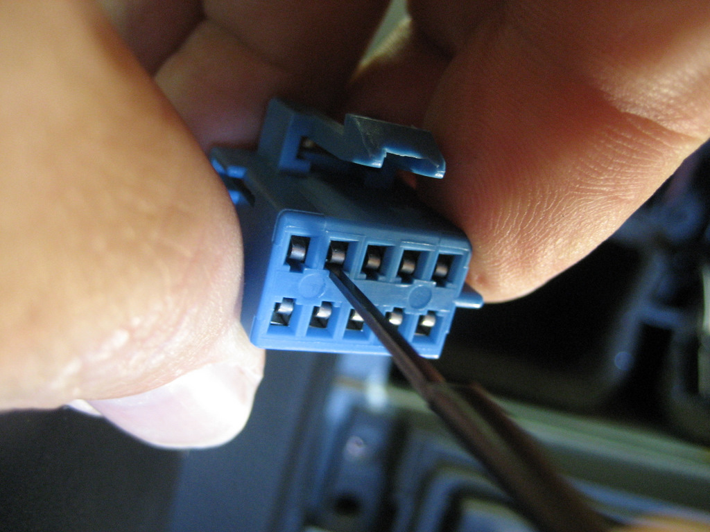
With a small jewelers screwdriver, you insert the
screwdriver into the bottom 3rd-from-the-right hole (position D) and
you can feel it riding up the ramp of the locking tab.
Push down (actually to the right in this photo) and this
will release the terminal.
Again, be SURE you have removed the TPA from the back of the connector.
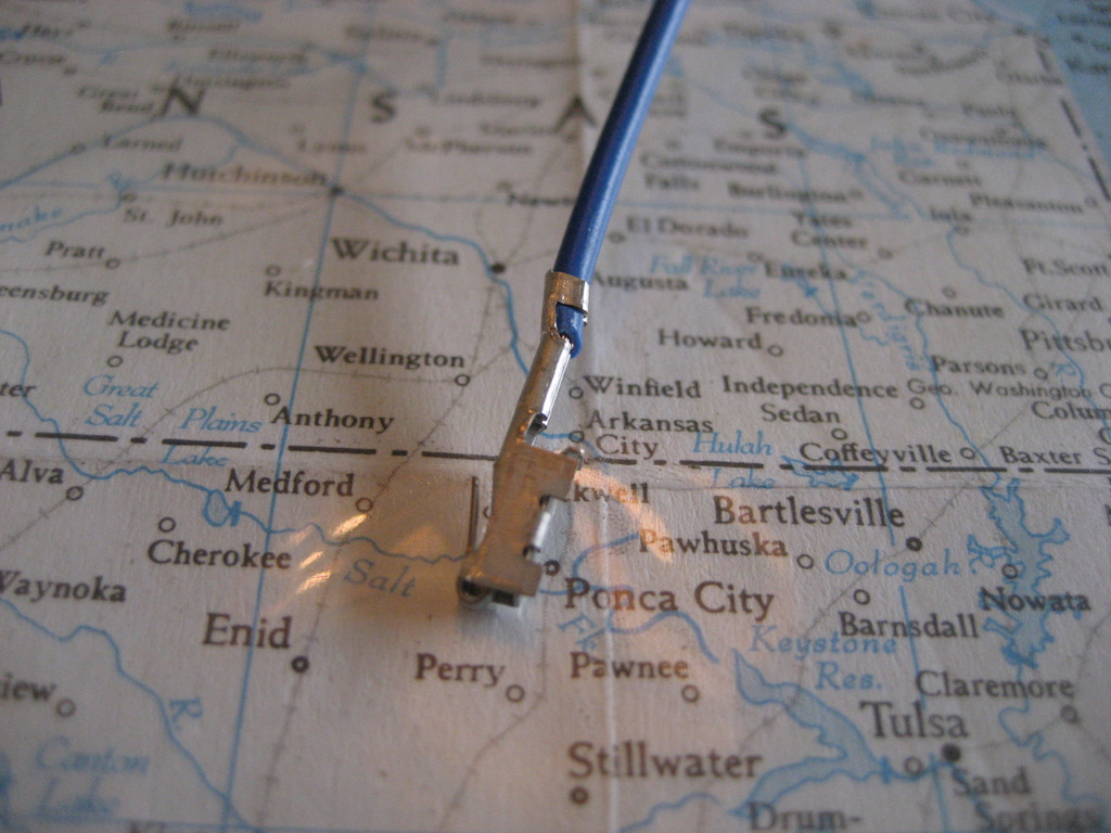
Gently pull on the terminal and if you released the tab OK,
it will come right out.
This is a bit tricky until you get used to the feel of that locking tab.
Here's what the green/white wire should look like coming
out:
OK, now you need some parts.
You can make an adapter harness by purchasing a Delphi 4
pin Micro-Pack 100 female connector, part number 12040904,
a Delphi 4 pin male connector, part number 12040903,
two female terminals, part number 12146447,
and two male terminals, part number 12084449.
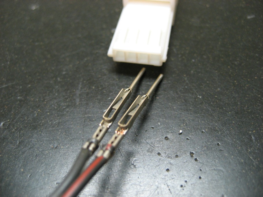
Here's the female side of the adapter harness:
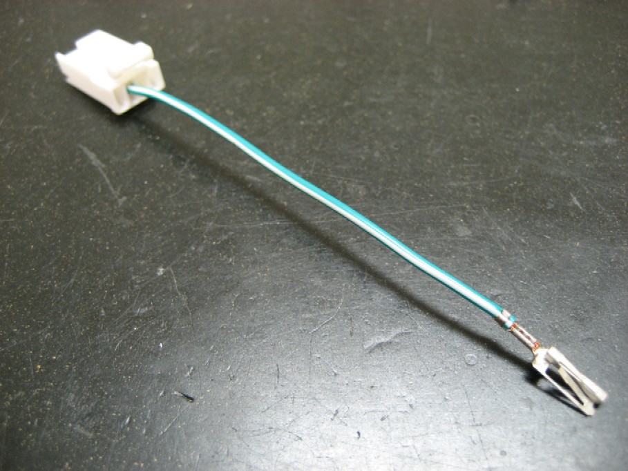
You crimp the two female terminals to a short
piece of 18 gauge wire.
Insert one end into the 4 pin female connector (only the
middle two of the 4 positions are used).
Here's a closeup of the new connector:
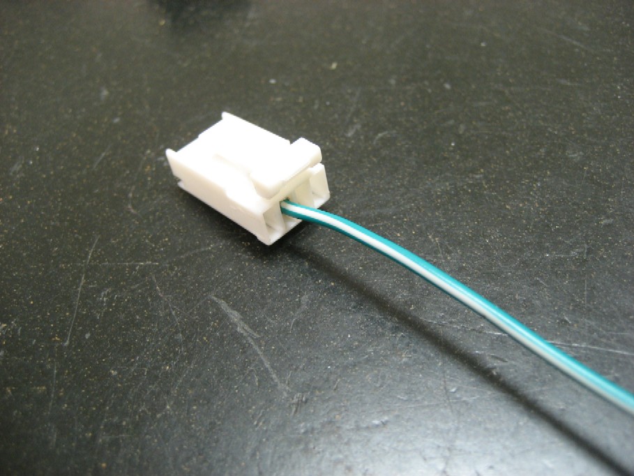
And another:
See the four locking buttons? One of them is up.
By pushing down on the locking buttons, this
provides a secondary assurance that the terminal will not pull out.
Next,
insert the green/white wire you removed from the 12 pin
connector into the 4 pin connector:
and push down the last locking button.
Now, insert the other end of your wire into Pin D of the 12
pin connector:

Reinstall the TPA:
Now we've got a new connector installed:
See all four locking buttons are pushed down.
And another view:
Now we need a pair of wires for the switch and the mating
male connector.
Crimp the male terminals (part number 12084449)
onto one end of your switch wire:
and insert them into the male connector (part number
12040903:
Push down all four locking buttons.
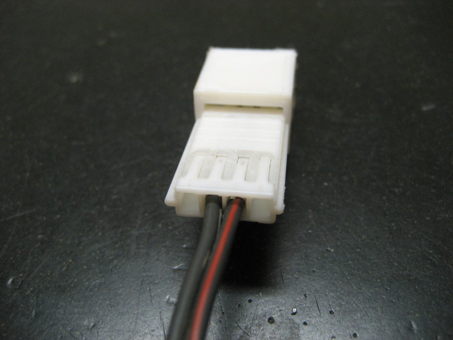
Now we have a new switch connector that will plug into the
new female connector:
Plug the connectors together:
and add a couple of tie straps:
and plug the 12 pin plug back into the Nav unit:
Reinstall the Nav unit and the heater controls:
Then run your new switch wires to the location you've
chosen for the switch.
Reinstall the console and you're done.
The hard part of this alternative is finding those Delphi
parts. You MIGHT find the terminals at your friendly Chevy dealer, but the
connectors are very tough to find, especially the 12040904 female
connectors. The 12040903 male connector was used in some older Pontiacs,
so you might luck out there.
Once you get your parts, you'll need to crimp the
wires to the terminals. The connectors have a fairly tight tolerance and
the terminals are made to be crimped rather than soldered. I bought a
special crimper for about $30 plus shipping from Ballenger Motorsports.
Here's their link:
http://www.bmotorsports.com/
Ask for their Tool-01000
ORDERING
You have the information to build your own adapter harness,
but if you want one already made up from me, send me $25 (Paypal or a check) and your address and
I'll get one coming to you. This NAV-1harness will include both connectors, the double
ended female wire to connect back into your 12 pin plug, and a 2' switch wire to
connect to the your switch. The terminals will all be crimped to fit the
connectors. The switch and switch terminals are not included, because each of you might have a
different idea of what kind of switch you want and where you want to mount it.
Email me at ray@kawal.net
if you have questions.
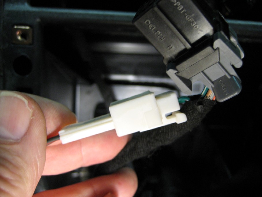
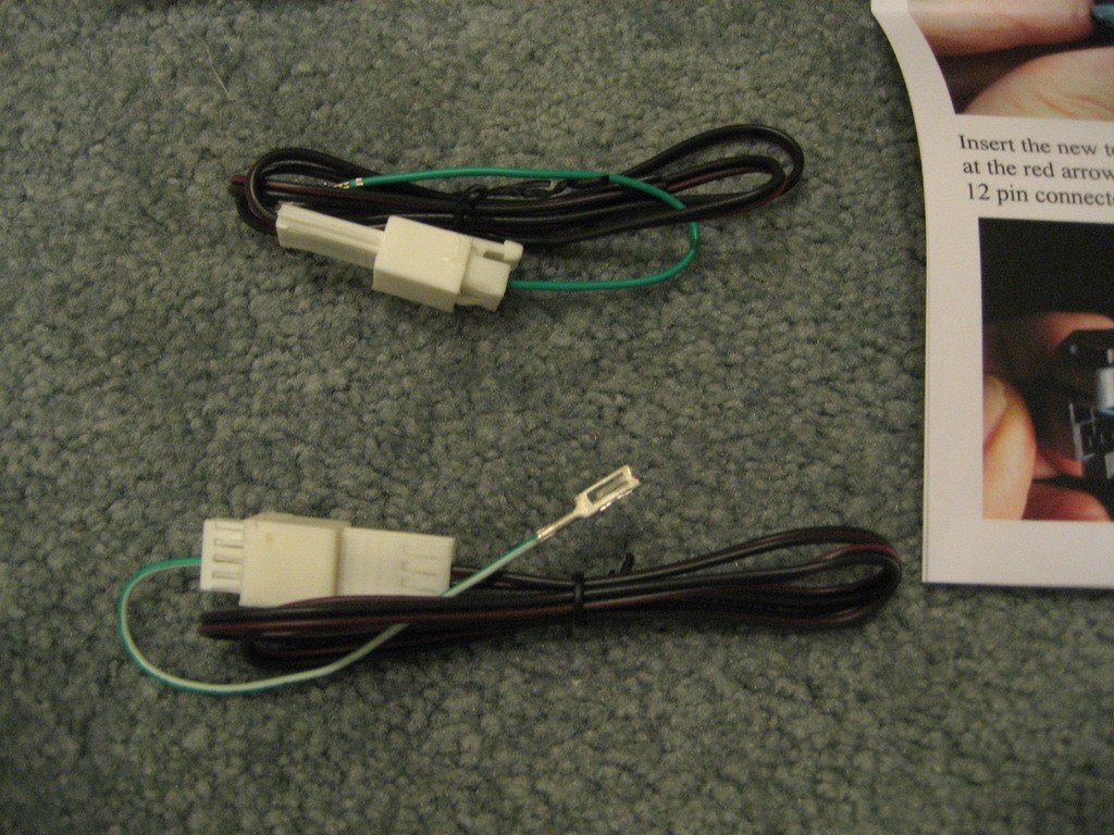
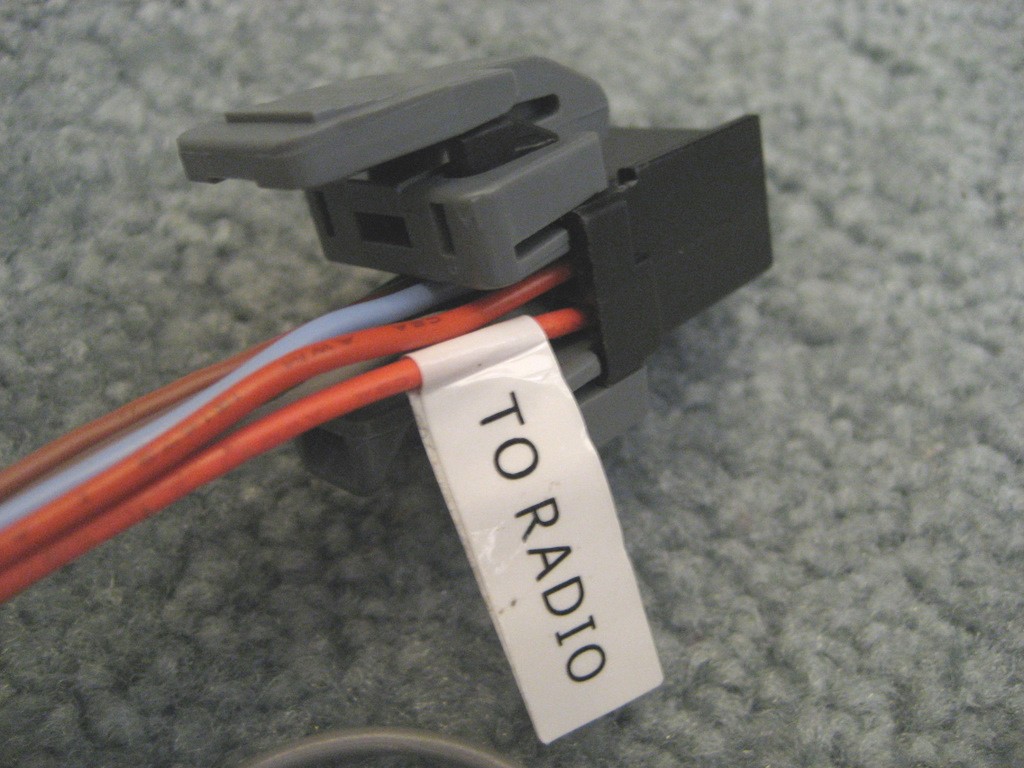
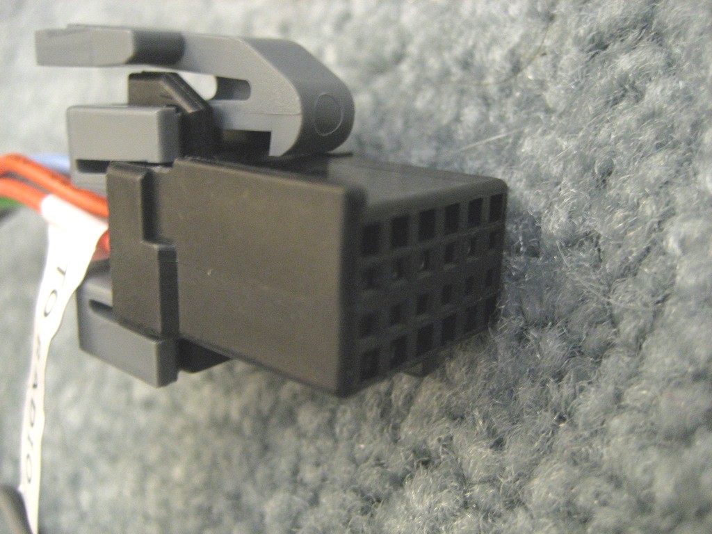
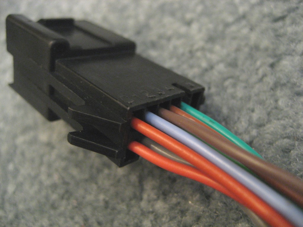
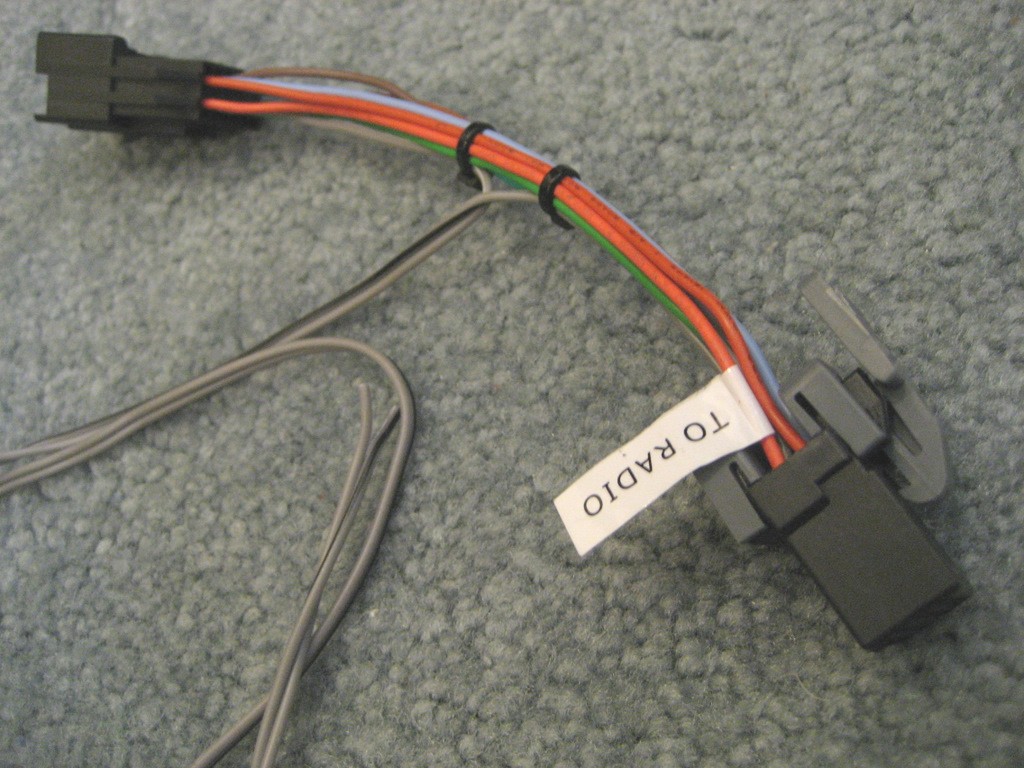
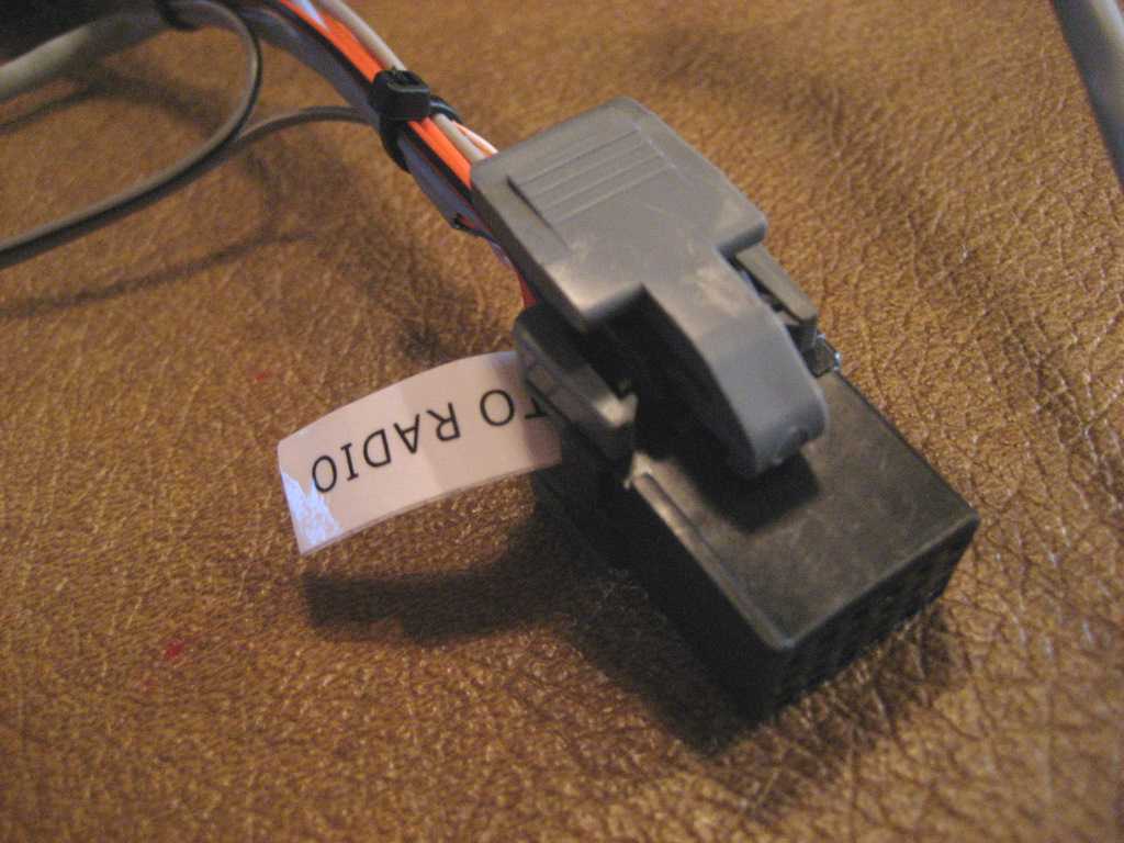
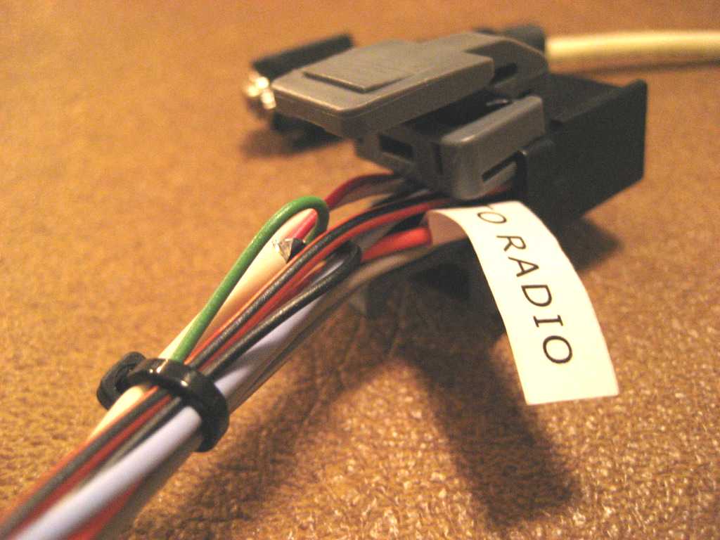
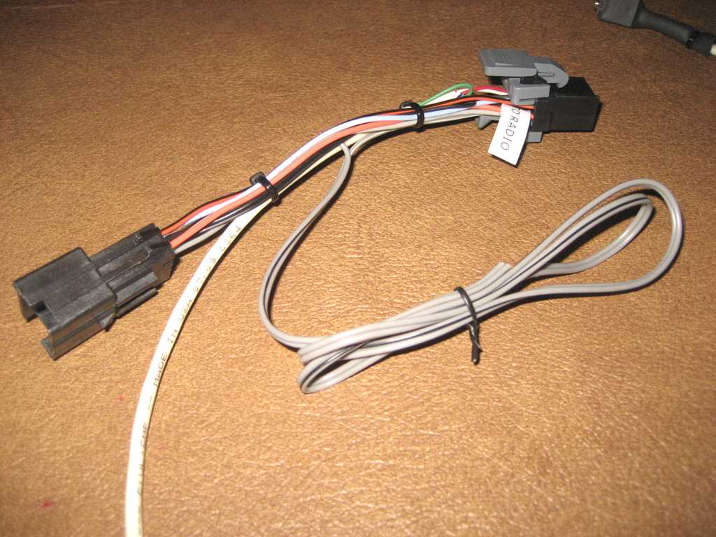
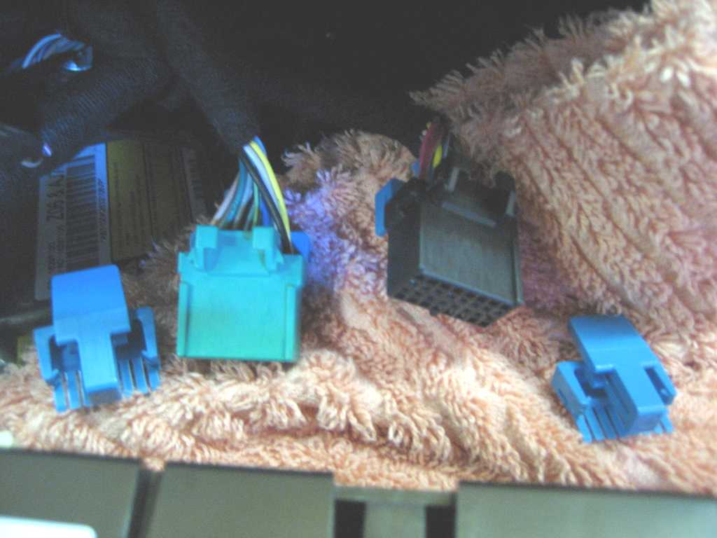
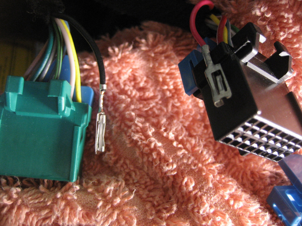
Here are a couple of photos
of the NAV-1 harnesses to show what is included:
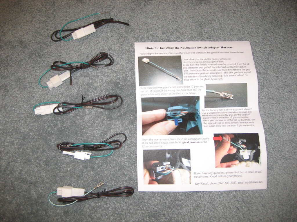
And a closeup photo:
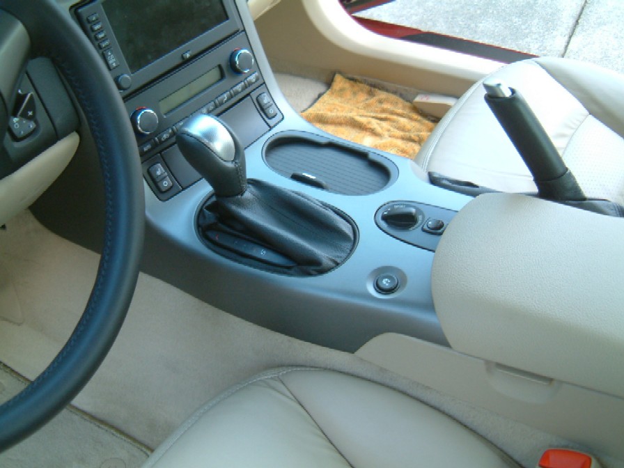
My buddy with an LT3 Coupe with the F55
Selective Ride Control Option
also wanted the mod, so we put it in his
Vette today.
Here are some photos:
You could also mount the switch on the
side of the console in the white area above.
The following photos will
help you with this modification.
Removal of the console
would be a five minute job if it wasn't for those pesky switch connectors.
Once you get them off, the
console comes right out.
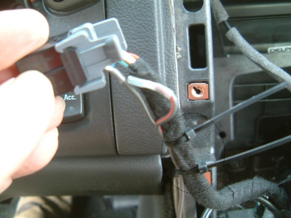
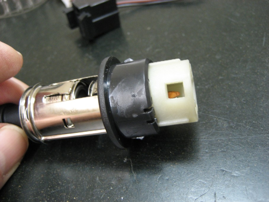
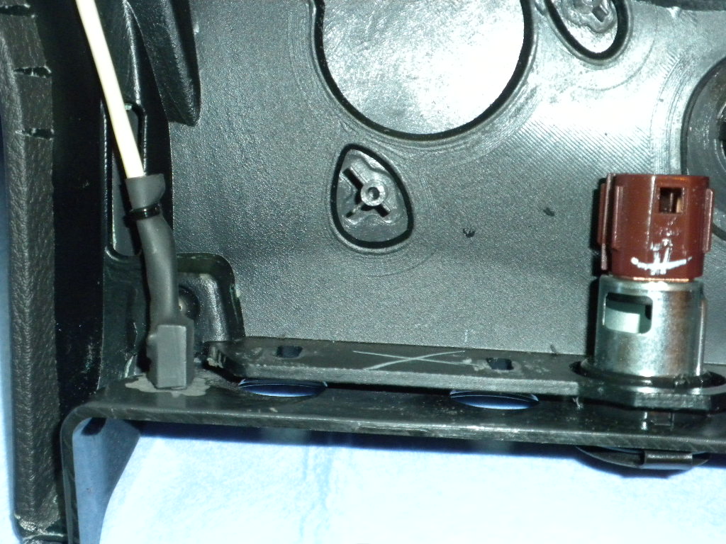
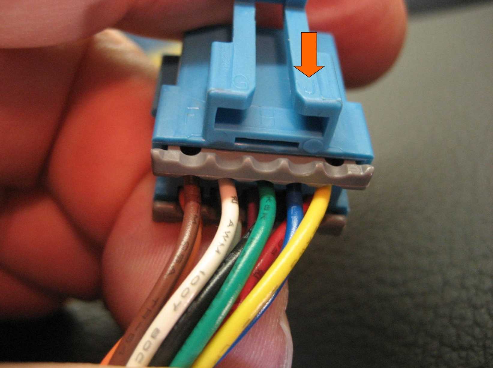
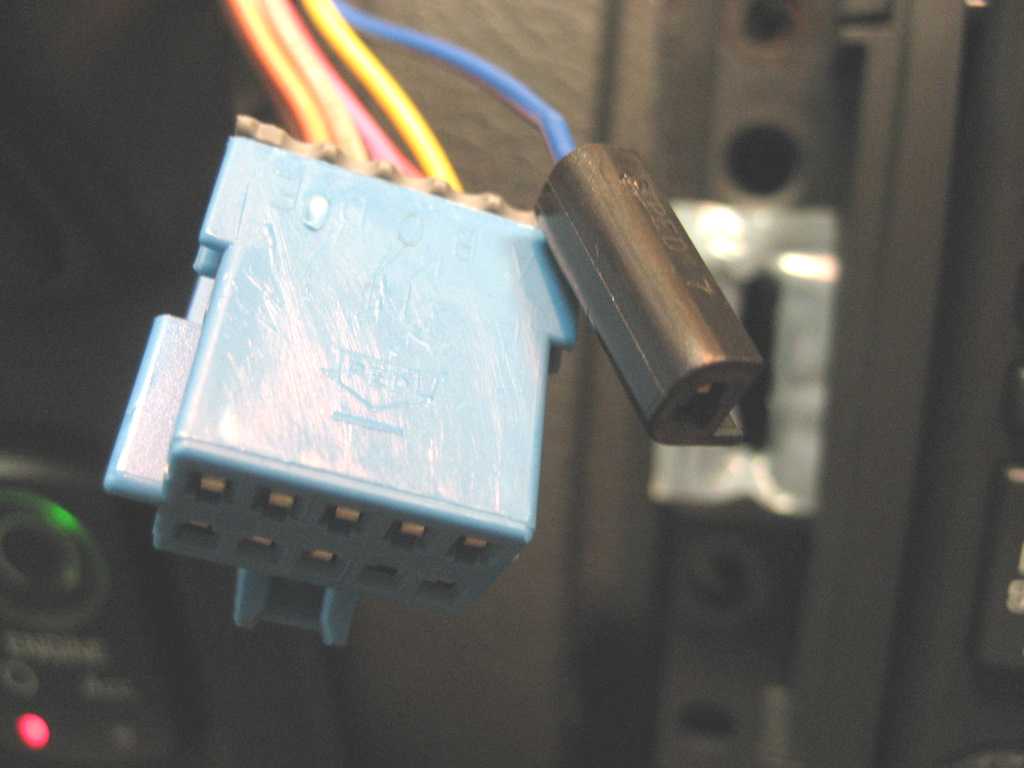
Perhaps the most difficult connector to unplug is the one
on the two power connectors (cigarette lighters):
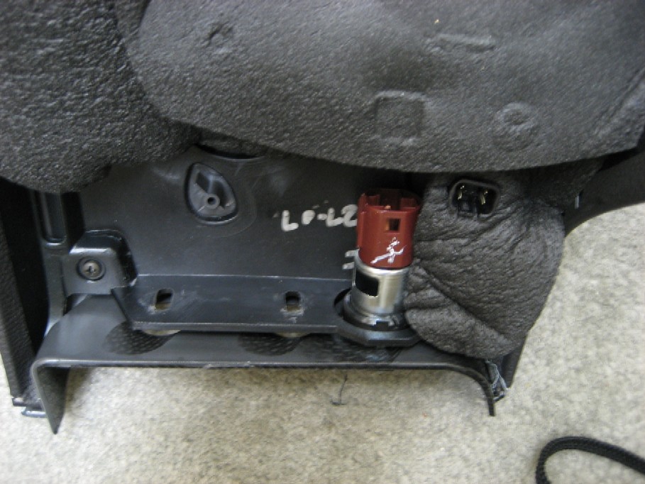
See the little square hole in the brown part? That is
sometimes facing down (as shown) or sometimes up, if your unlucky.
But the locking tab is in that square hole. You need
to get a small tool to push in on the tab and once released, the connector will
come right out.
Here's another view of the power connector after it has
been removed from the ashtray assembly:
Remember, there are two of these connectors - one in the
console and one next to the ashtray.
You only need to remove this if you
are going to use this location for your switch.
This isn't particularly fun to remove, but here's how you
do it:
1. See the black plastic ring on the connector/lighter
assembly? When it is locked in place, this ring is slid all the way to the
left in this photo, along the chrome metal tube that the lighter plugs into.
2. To remove it from the ashtray, you must be able to
press in the two black locking tabs seen at the top and bottom of the black
ring. This allows it to be released from the hole in the ashtray.
But those locking tabs cannot be pushed in until the black plastic ring is slid
along the tube to the position shown in the photo.
3. So to get the plastic ring slid down the tube to
this position, you need to unlock it from the tube. I'm sure GM has a
simple tool for this, but here is what I did:
A. See the square hole to the
right of my thumb in the photo? Now look to the right at the plastic ring
and you will see the locking tab that locks into that hole. There are two
of these holes and locking tabs (unfortunately), one is on the other side that
you can't see in the photo.
B. This is tricky, but if you
remove the lighter and look down inside the tube from the front, you will see
the two square holes with the locking tabs in them.
C. You must push both locking
tabs out of the square holes, while you push the tube from behind. The
black plastic ring will stay in place on the ashtray while the tube will come
out the front. Without the proper tool, I used two small jewelers
screwdrivers to push hard on both locking tabs while pushing the tube out the
front. You need about six hands to do this, but with a little luck,
patience, and swearing, the tube will pop out the front.
4. Once you get the plastic ring slid down the tube
into the position shown, you should be able to pull the entire lighter assembly,
including the black plastic ring, out of the ashtray assembly. This is
because the two other locking tabs shown at the top and bottom of the plastic
ring will collapse when the ring is in this position.
5. If you ever need to install the lighter/power
connector back into the ashtray or console or whatever you are mounting it to,
it is really simple. You just push the plastic ring into the hole and push
the tube into the ring. So you can see how simple and quick that would be
at the factory. But getting it out is another matter. There is
probably a tool that allows you to push the tabs in the square hole and lock the
tool into those same holes and pull the entire assembly out. Maybe your
local auto parts store might such a tool, but it is probably too expensive to
buy for a one time job.
Note: One owner suggested that you remove the entire
ashtray assembly from the console before removing the connector/lighter
assembly. There are only 5 screws holding it in place. I didn't take
mine out of the console first, but since it's simple to do, you can decide what
is easier for you.
Another sometimes tricky connector is the Hazard Warning
Switch:
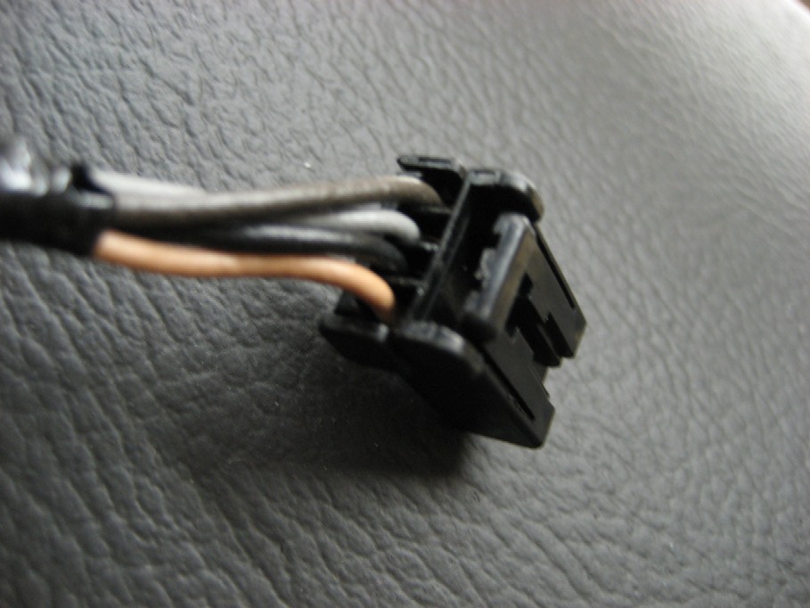
The release tab is on the right in the photo, towards the
ground when in the console.
Push toward the wires to release it.
Here's the switch:
The heated seat switch connector is pretty easy to release:
The release tab is on the top in this photo, but on the
bottom when inserted into the switch:
Remember there are two of them.
Before you try to remove the console, remember to first
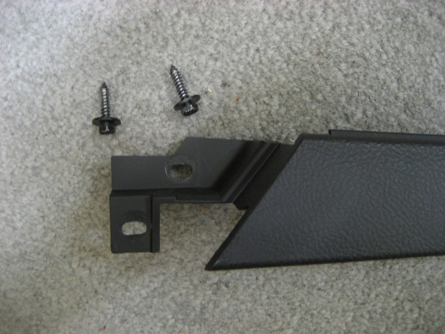
remove the side trim:
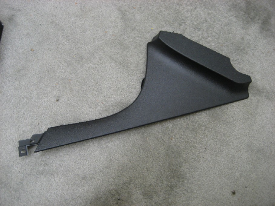
First, remove the two 7mm screws by pulling up the front of
the E-brake boot:
Then pull out and up to release the clips on the front of
the trim:
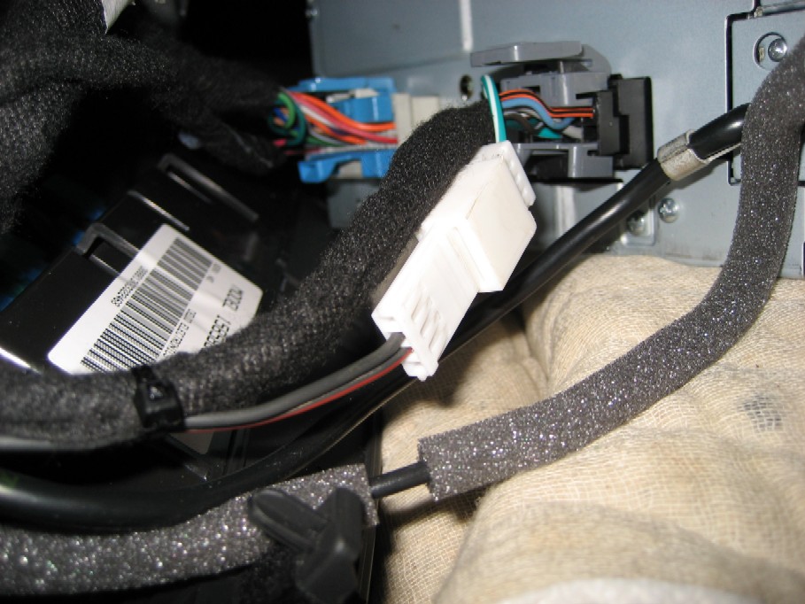
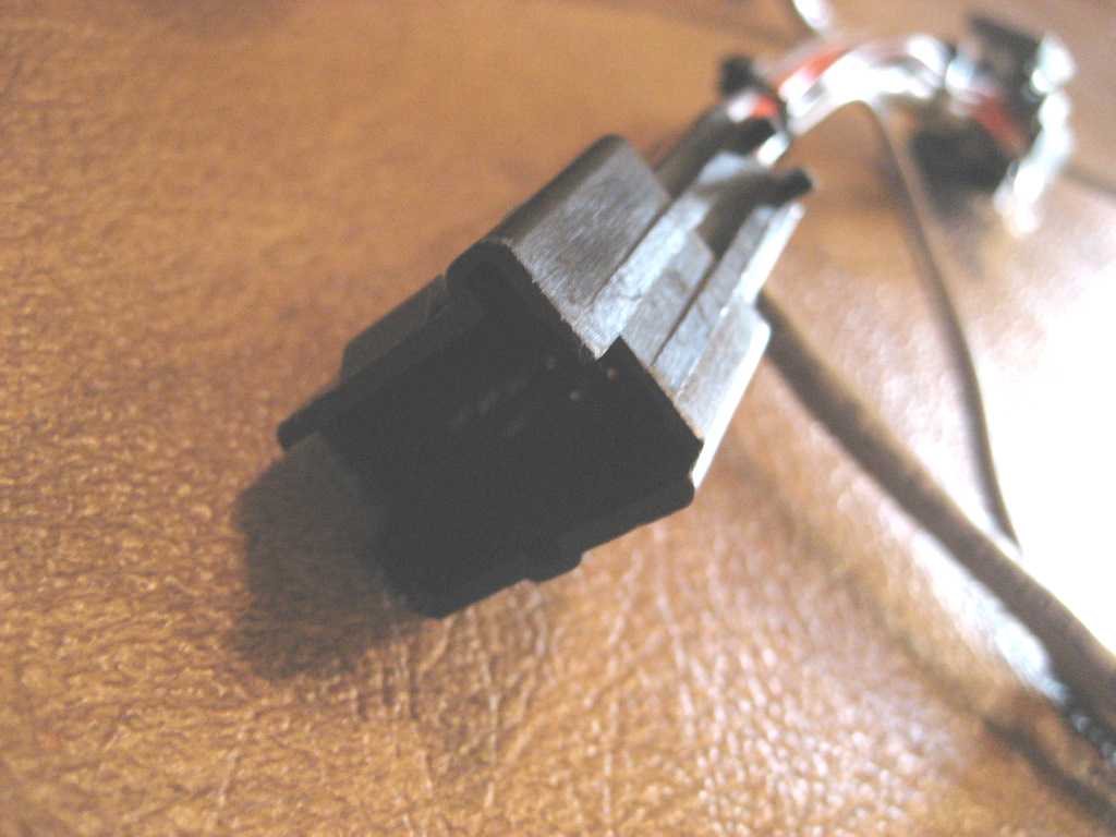
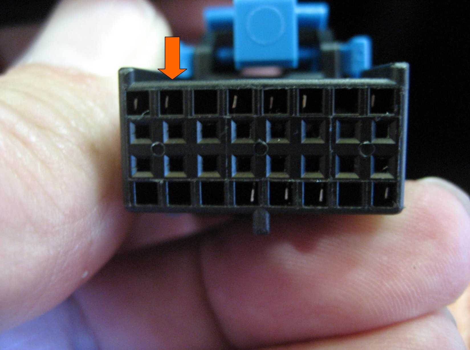
Here's a closeup photo of the 12 pin plug:
If you look closely at the hole on the bottom, third from
right, you can see the part of the terminal where the locking tab is.
You'll want to insert your jeweler's screwdriver into that
hole and feel it go up the ramp of the locking tab.
Then push towards the right of this photo to release the
terminal.
Click
Here for Ordering Information
Alternative
3:
(The NAV-2 harness)
Connect the new switch using
a custom NAV-2 adapter harness that is simply plugged in (cost $45 plus the switch).
Alternative 2 above shows
how to make an adapter harness to avoid cutting the factory wiring
harness. As noted in the discussion, you can purchase the NAV-1 harness from me
for $25 if you wish. This third alternative is another custom adapter
harness (NAV-2) for $45 that is even simpler to install:

To use this harness, there
are four steps:
1. Unplug the 12 pin
connector from the back of the Nav radio.
2. Plug that 12 pin
connector into the mating connector on the harness (shown at left).
3. Plug the new 12 pin
connector on the harness into the Nav radio (shown at right).
4. Connect your switch
to the new wire pair shown in the photo.
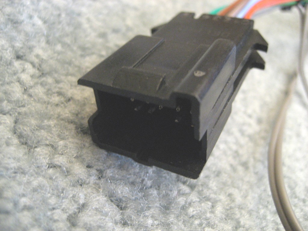
Here are some more photos of
the NAV-2 harness connectors:
The above connector is the
same Delphi 12064799 connector that is part of your factory wiring harness.
This 15356627 Delphi
connector mates with the Delphi 12064799 connector:
Closeup photo of the adapter
harness:
Click
Here for Ordering Information
Alternative
4:
(The NAV-3 harness)
Same as Alternative 3, but
Adding an Auxiliary Input to the Nav radio for connection of your music device.
You might recall from the first discussion of this Navigation modification, that the speed sensor
wire is Pin D of the 12 Pin Radio connector:
But take a closer look at
Pins H, J, and K of that same connector above.
Pins H, J, and K are the
audio input wires from the XM receiver.
By modifying the NAV-2
custom harness described in the previous section, we can intercept these audio
signals and use them for an Auxiliary Input from another music device.
Most devices utilize a 3.5mm (1/8") jack on the device to connect speakers
or an earphone. The latest C6 Corvettes have a built-in Auxiliary Input
jack on the radio faces, but the Navigation radios still do not have an
Auxiliary Input. So we can add that Auxiliary Input to the Nav radios with
this custom harness.
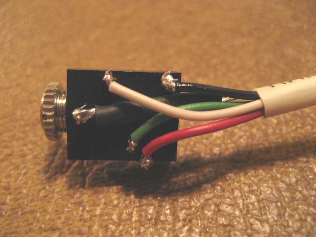
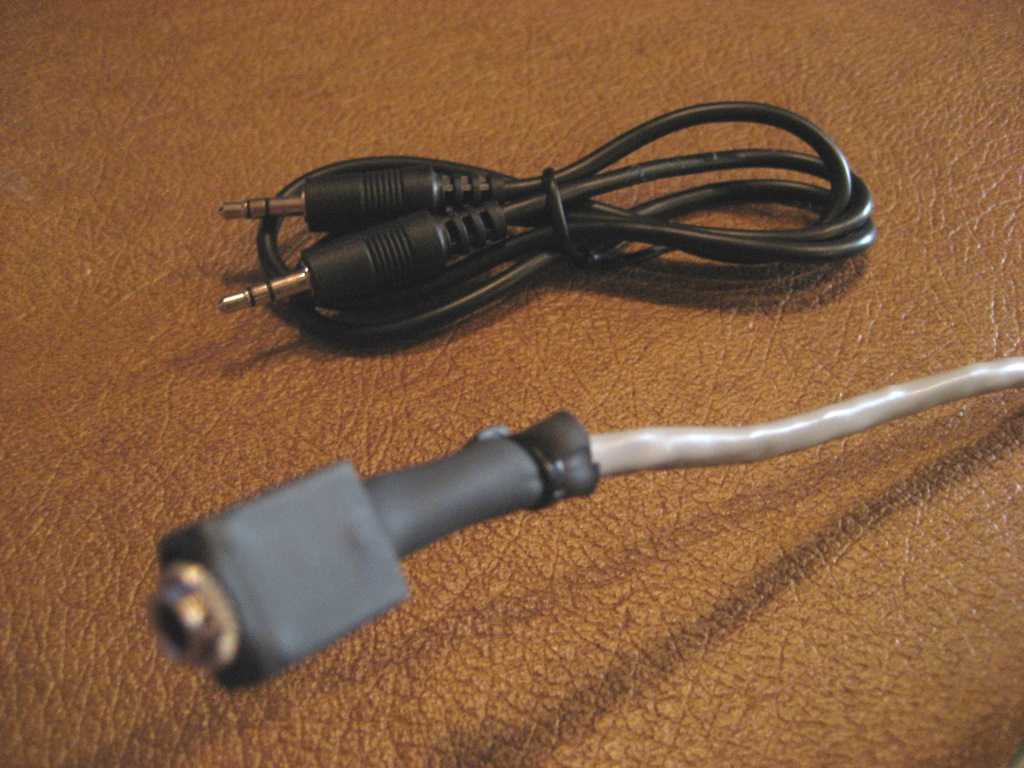
Here is what the NAV-3
harness with Aux In looks like:
It still has the same wire
for the speed sensor switch, but we can add a 3.5mm (1/8") jack that will
disconnect the audio from the XM receiver when a 3.5mm stereo plug is inserted
and connect your music device to the audio system instead of XM. When you
remove the plug, the jack reconnects the XM receiver audio.
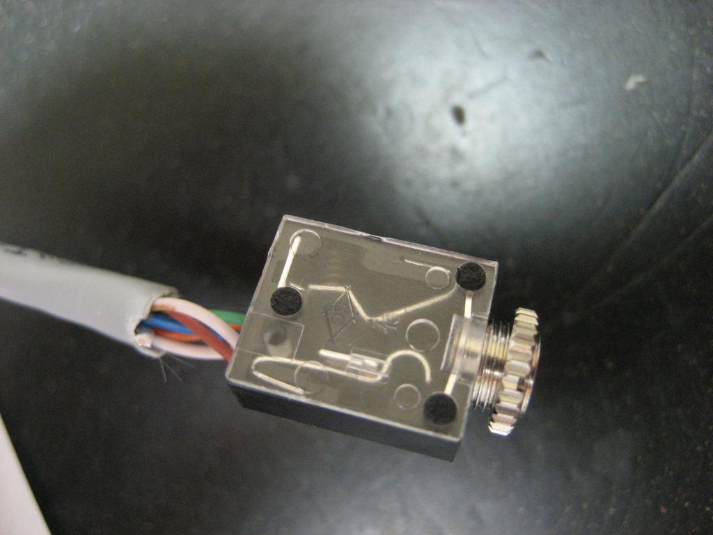
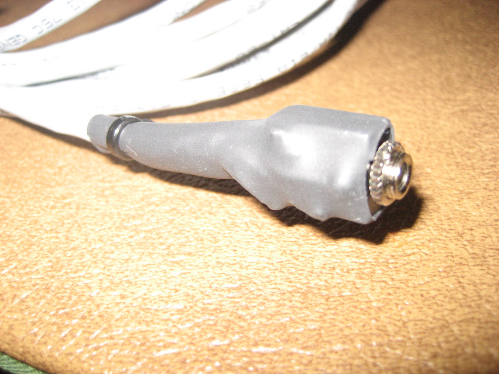
Here is a closeup of the
jack:
Click
here for a .pdf file showing the jack and wiring details
When
a 3.5mm stereo plug is inserted into the jack, audio from the XM receiver is
disconnected and audio from the plug is connected.
Here
is a photo of the jack wiring:
Here
are additional closeup photos of the NAV-3 harness connectors.
First the Aux In jack:
The soldered connections are
under the heat shrink tubing.
This jack requires a
1/4" hole to be drilled somewhere convenient near the center console.
A suggested location would be the right side console trim plate:
Here is a photo of the NAV-3
radio connector:
It is exactly the same
Delphi connector as the OEM 12 pin radio connector, Delphi part number 12064799.
Here is the wiring from the
rear:
The audio wires are in Pins
H, J, and K in the above photo.
Here are the Delphi Micro
100 female terminals used in the radio connector:
Here is a photo of the body
harness connector that accepts the OEM 12 pin connector you remove from the Nav
radio:
This is the same Delphi
15356627 connector used in the NAV-2 harness.
But the audio wiring is
different:
Note the audio wires
in Pins H, J, and K (positions C3, 4, and 5 on the connector).
Here is a photo of the male
terminals used in the body harness connector:
Here is a photo of both 12
pin male and female connectors:
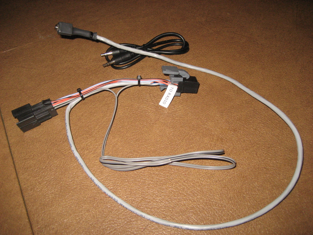
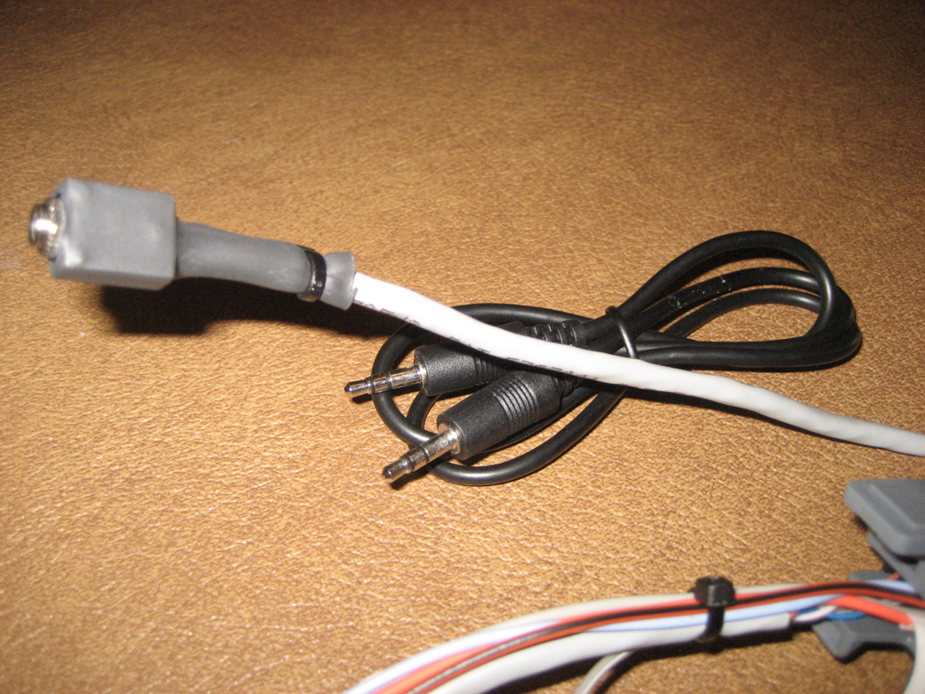
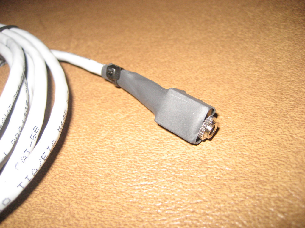
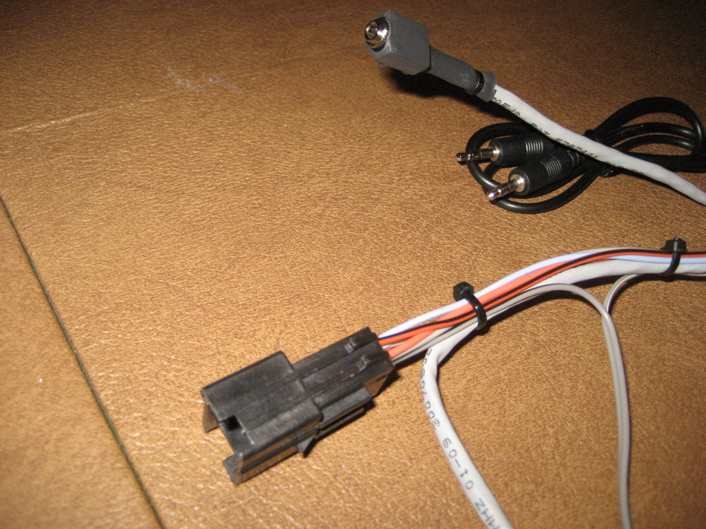
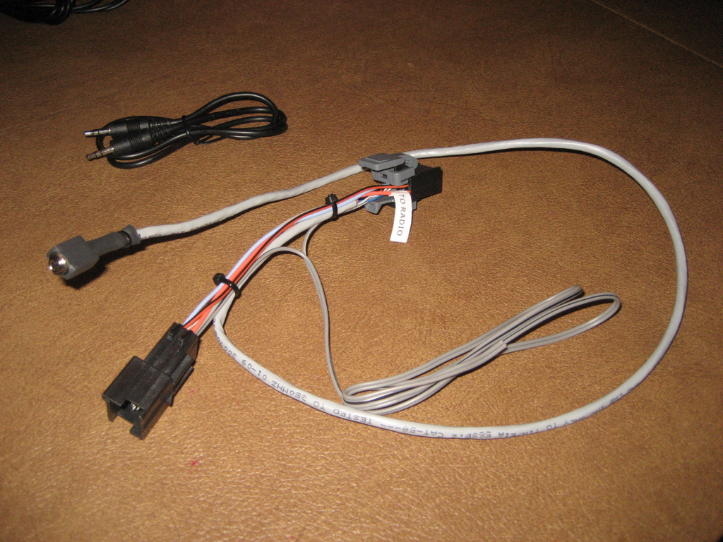
Here is a photo of the Aux
In jack and patch cable to connect your music device:
Here is the complete
harness and patch cable:
Here are some photos of
Les Wilson's Aux Jack Installation:
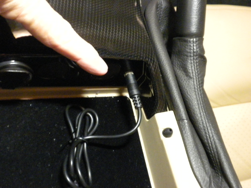
On the left, above, is
the Aux In jack mounted in the console.
All you need is a 1/4" hole.
But note that the threads on the jack are pretty short and the jack is really
made for a panel about 1/8" thick.
Les used a Dremel tool to
grind a bit of the console to make it a little thinner so the jack would fit.
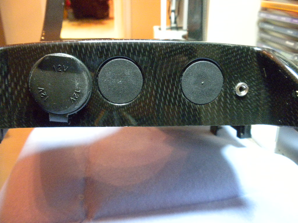
Here's another installation
example from owner Jeffrey Carlson:
He also used a Dremel tool
to grind away a bit of plastic to make the jack fit the panel.
He used a 15/64" drill
bit.
ORDERING
You can make your own
harness using the instructions above and the .pdf file for the jack if you
choose the NAV-3 design. But the connectors and terminals are often hard
to find.
FOR A KIT TO BUILD YOUR OWN HARNESS:
The NAV-3 harnesses are labor intensive, so for those of
you who have the experience to build your own, I can offer a complete kit of
parts to build the harness for $40 plus $5 for Priority Mail shipping. The
kit will consist of the following:
12 pin Delphi Male and female
connectors
Delphi Micro 100 terminals to fit the connectors
3.5mm switched jack
3' of 4 conductor plus shielded 22 gauge stranded wire
2" piece of heat shrink tubing for the jack
3 nylon cable ties
To install the terminals, you will need a crimp tool.
If you don't have one, click
here for a suggested tool from Ballenger Motor Sports.
FOR A COMPLETE HARNESS:
If you prefer, I can make
you a complete harness of your choice. The simple NAV-1 harness is $25
including shipping, because it is so light and easy to mail. The NAV-2
harness is $45, but you'll need to add $5 for Priority Mail shipping
because it requires a small flat rate box. The NAV-3 harness is much more
time consuming to make because of the soldering and additional wiring. So
I'll need $90 plus $5 Priority Mail shipping if you choose that route.
Remember that these harnesses do not include the switch for the speed sensor
disconnection because you'll need to choose your own switch and location for the
switch. The NAV-3 harness does include a 2' patch cable to connect your
music device. I also have 6' patch cables if you would prefer the longer
length.
You can email me at ray@kawal.net
if you have any questions about this installation or would like to order a
harness.
Click
here for a link to my Ordering Page
Alternative
5:
Install Ben Stanley's Sunset
Orange Creations Navigation Commander (see
Ben's site for cost).
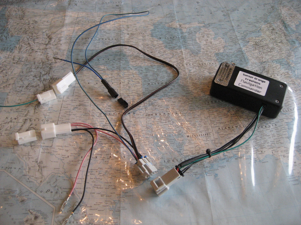
This wiring harness will
allow installation of the Sunset Orange Creations Navigation Commander with Delphi
connectors and no harness wire cutting:
For those of you not familiar with Ben's
Navigation Commander, it offers a couple of nice features:
1. A new switch is not
necessary. Instead, the Commander circuitry allows you to use the TRIP
button on your DIC to switch out the speed sensor signal to the Nav unit.
This makes the installation look completely "factory".
2. As noted in the discussion of
Alternative 1, when you switch out the speed sensor signal, you have a limited
time to enter destinations before the Nav unit "figures you
out". What happens is although the speed sensor signal is switched off,
the GPS eventually tells the Nav unit that you have indeed moved - so you again
lose your destination screen. With the "switch alternatives"
described above, if you run out of time, you have to switch back to
"normal" until the screen blinks, then again switch out the speed
sensor signal. Depending how much time you have taken to enter your
destination, this may or may not be an "irritation" for you.
With Ben's Navigation Commander, his circuitry automatically switches the speed
sensor signal back in after about 30 secs, then out again, and repeats that
until you have entered your destination. It works pretty nicely.
This Alternative shows a
method of installing the Nav Commander that Ben may or may not incorporate into
his package.
I prefer it because it uses
factory type Delphi connectors and you don't have to get into the fuse block
area to add piggyback type fuses.
These connectors are solid,
factory quality connections that are well integrated into the factory wiring
harnesses.
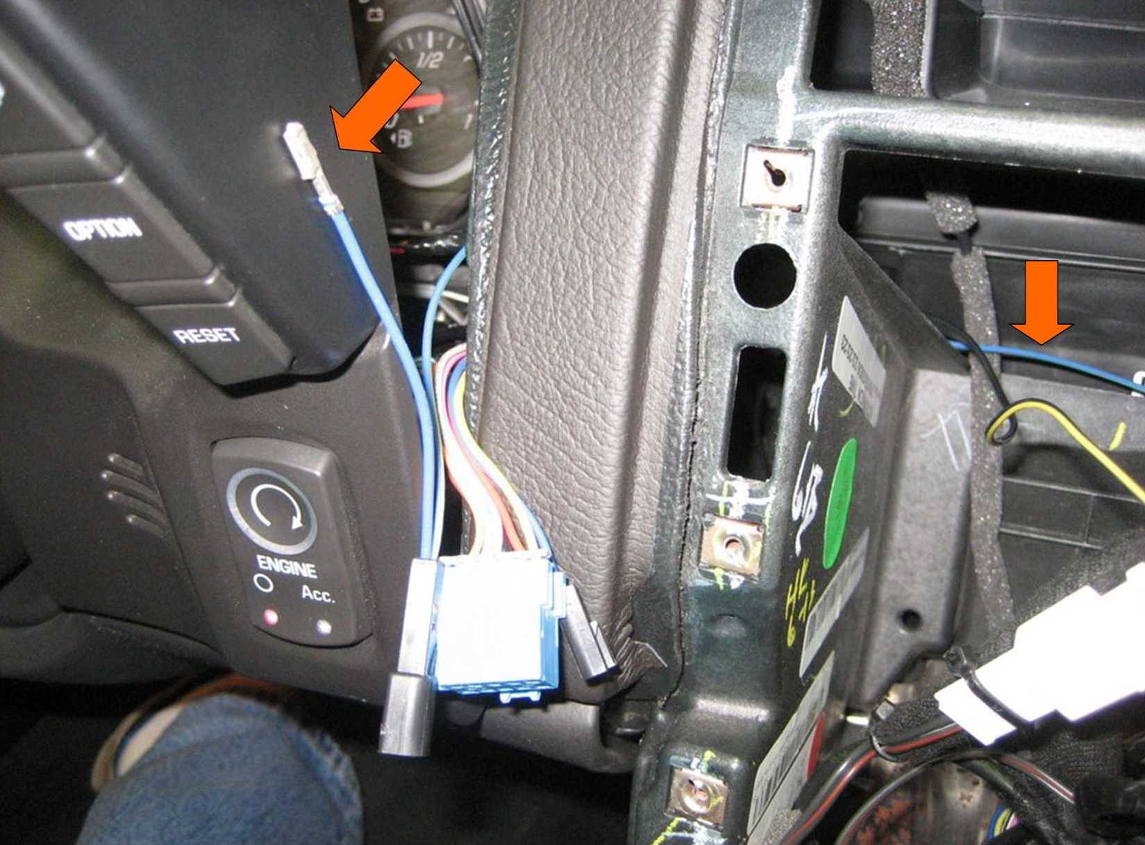
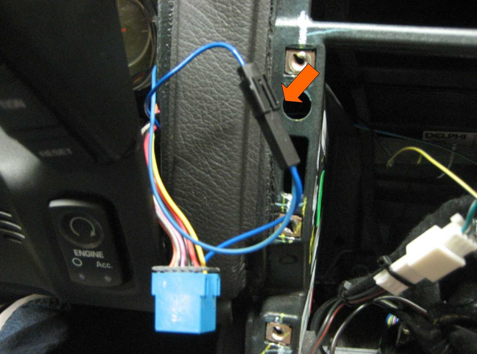
Five wires need to be
connected into the factory wiring harnesses:
A. Ignition and Ground
wires (pink and black) into the HVAC (heater controls) connectors.
B. Two wires into the
speed sensor terminal of the 12 pin Nav Unit connector.
C. One blue wire into
the Driver Information Center switch connector.
To get started, first remove
the center console. Then remove the two 7mm screws holding the HVAC
controls in place.
(At this time, leave the Nav
unit in place.)
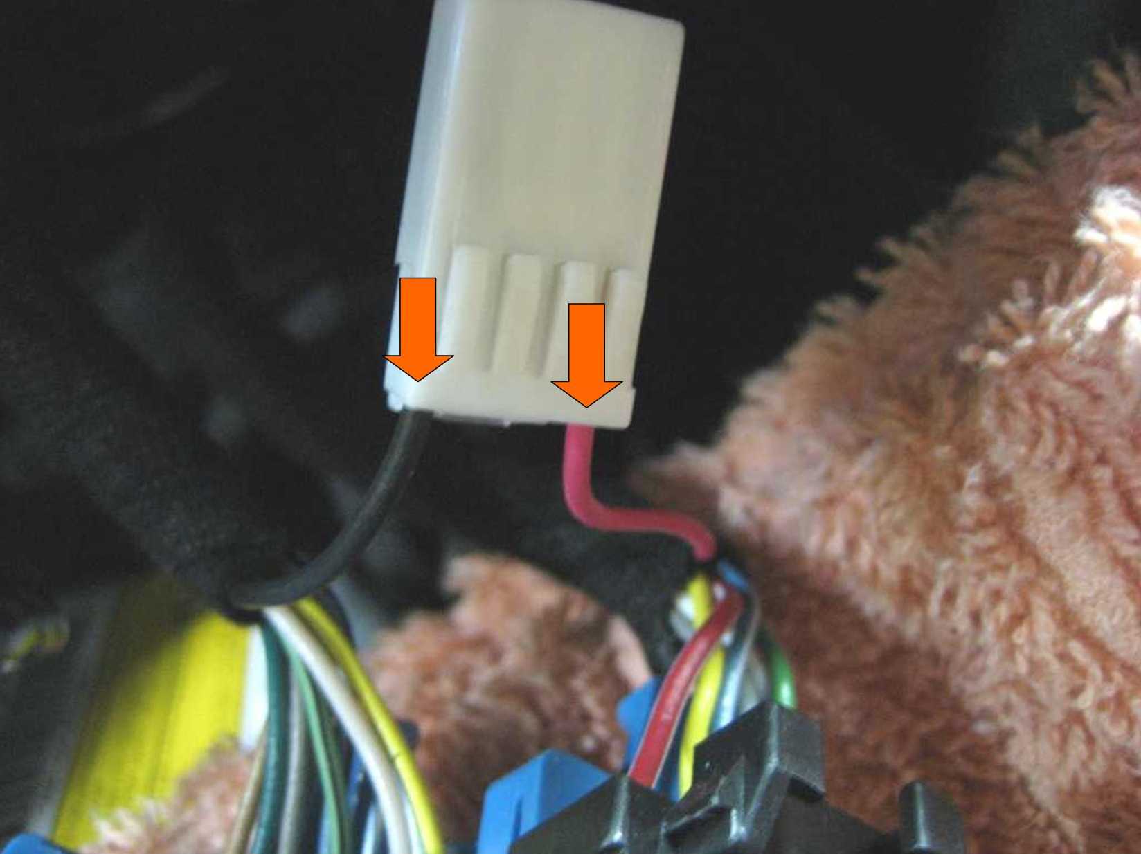
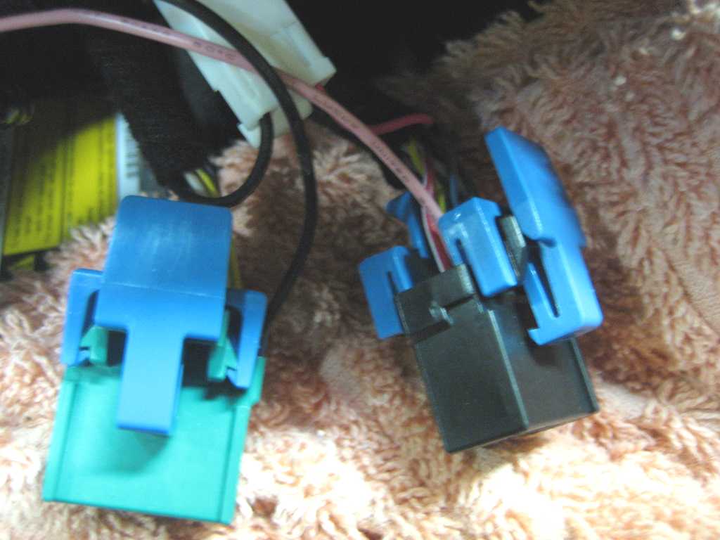
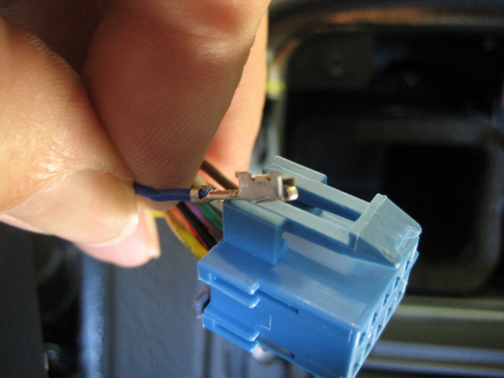
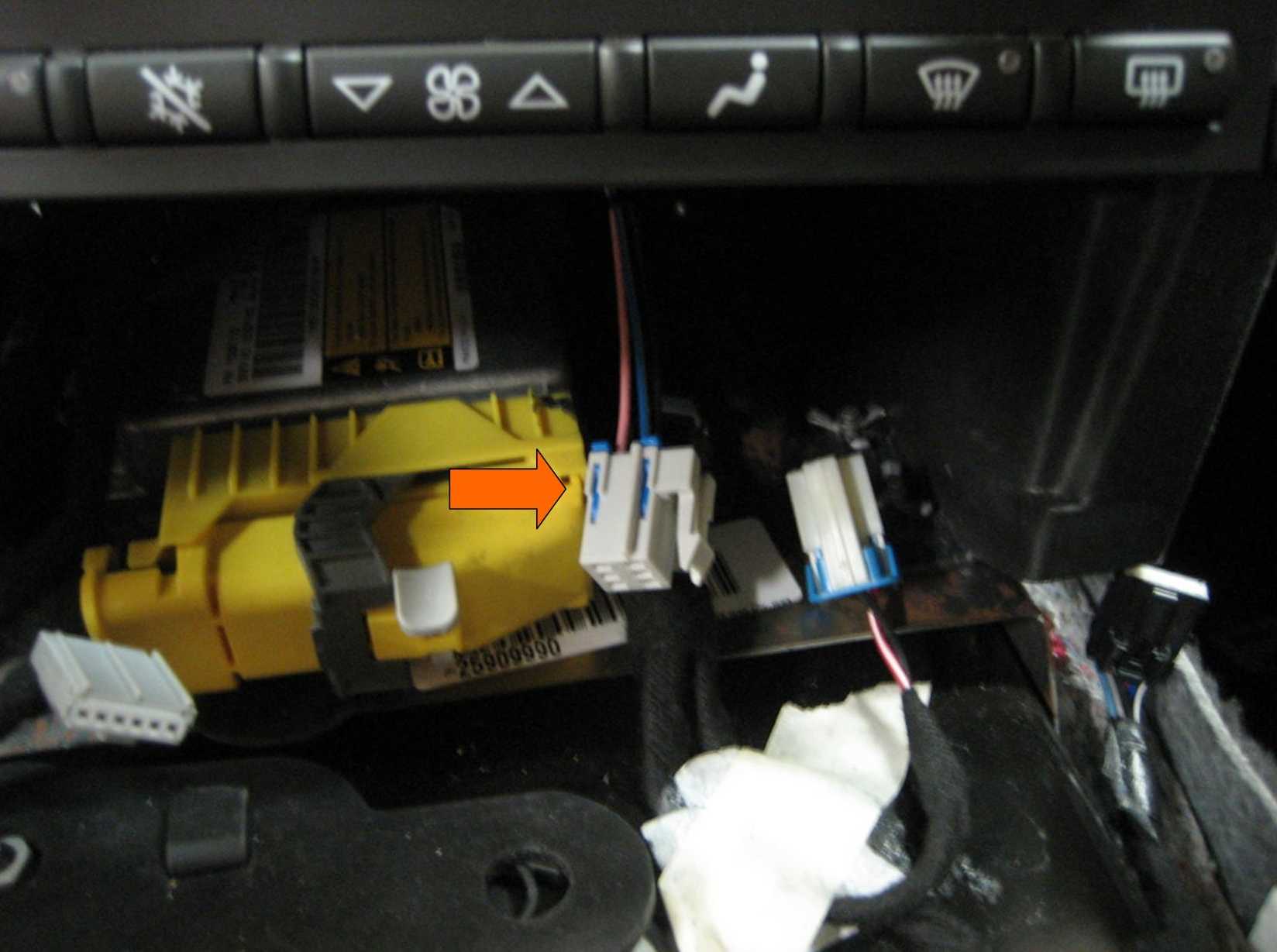
Unplug the green and black
connectors by squeezing the blue tabs on the TPAs:
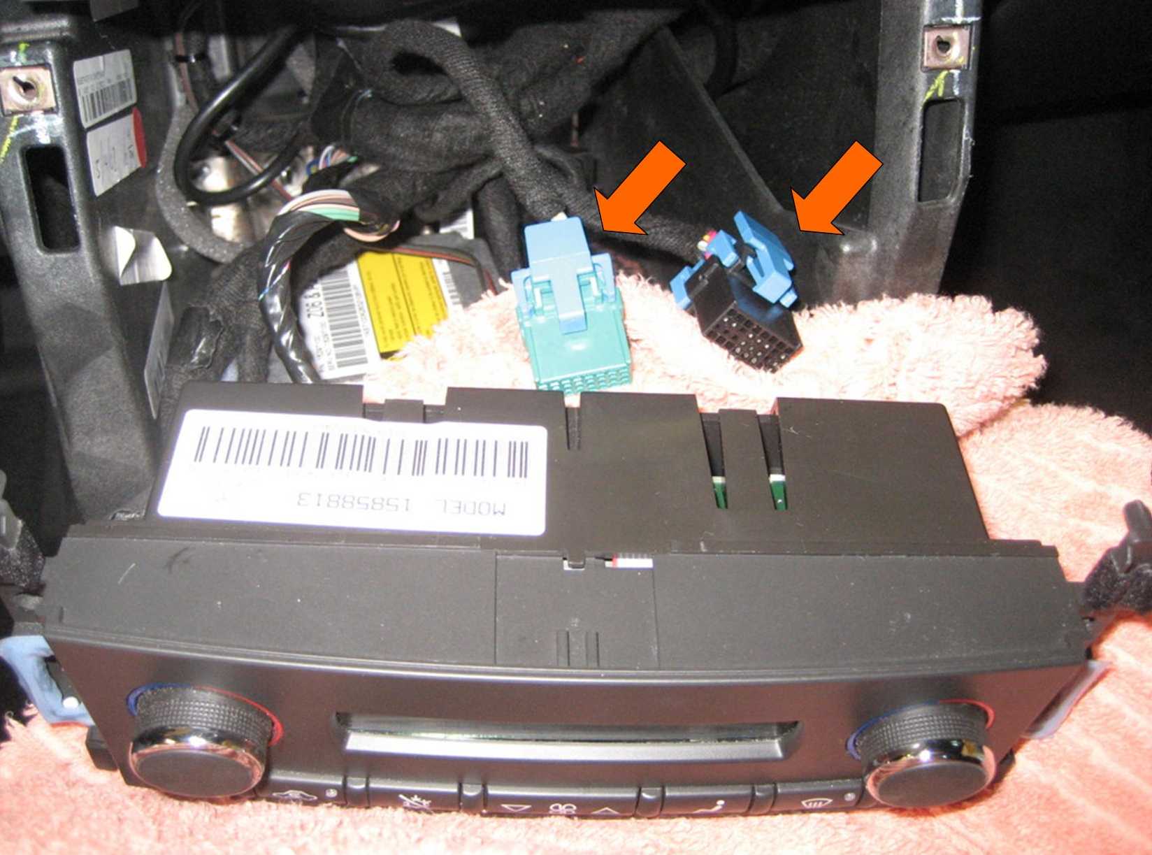
Examine the two
connectors. We want to remove two terminals, one from each connector.
On the green connector, we
want to remove the black Ground wire from Position A1 on the upper right:
The Delphi Micro-Pack 100 connectors have been used for
years in GM radios.
Here's what the terminal looks like up real close (on
another green/white wire):
See the locking tab? That needs to be pushed down to
release the terminal.
(Be sure the TPA described above is removed before you
attempt to remove the terminal!)
The middle 16 holes are where the terminals make their
electrical connections.
The top and bottom rows are where the locking tabs lock into the connector to
prevent them from coming out.
The terminal installs in the connector sideways, with the locking tab above the
square connection surface..
With a small jewelers screwdriver, you insert the
screwdriver into the top right hole and as you push to the left,
you can feel it riding up the ramp of the locking tab.
Push to the left and this
will release the terminal.
Again, be SURE you have removed the TPA from the back of the connector.
Gently pull on the terminal and if you released the tab OK,
it will come right out.
This is a bit tricky until you get used to the feel of that locking tab.
I find it easiest if you insert the screwdriver all the way
until it touches the back of the terminal (you'll feel it stop),
then push left to release the terminal.
In the other (black)
connector, we want to remove the pink Ignition wire from position A7.
A7 is next to the upper left
position:
In order to remove these
terminals, we must first remove the TPAs (for Terminal Protection Assurance).
There are two TPAs on each
connector. You only need to remove the top ones.
Just pry them off with a
small screwdriver:
Using a small jewelers
screwdriver, remove the black Ground wire from the green connector (seen on the
right in the above photo)
and the pink Ignition wire
from position A7:
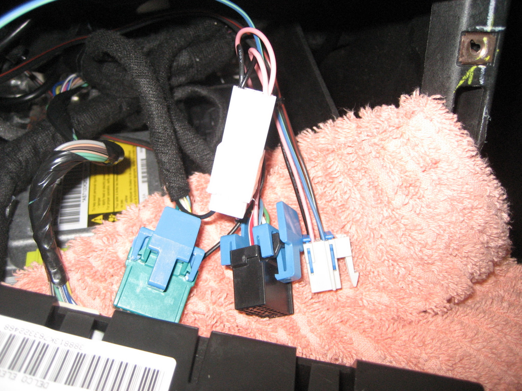
Insert both wires into the
outside positions of the white female connector:
Push the four locking tabs
to hold the terminals in place.
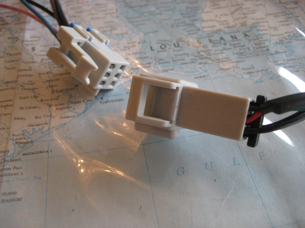
Next, examine the white
connector on the harness for the Ground and Ignition Wires:
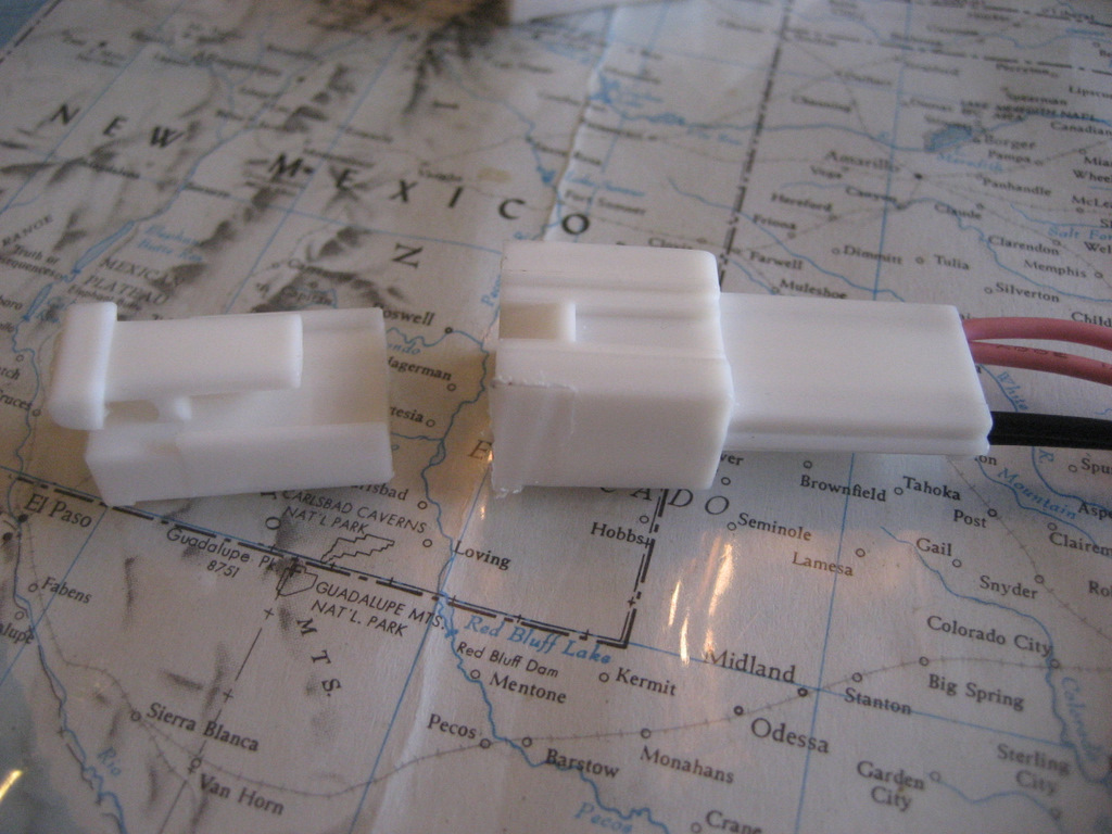
On the left is the connector
you just attached to the two original Ground and Ignition terminals.
On the right is the
connector attached to the harness.
See the two new Ground and
Ignition wires?
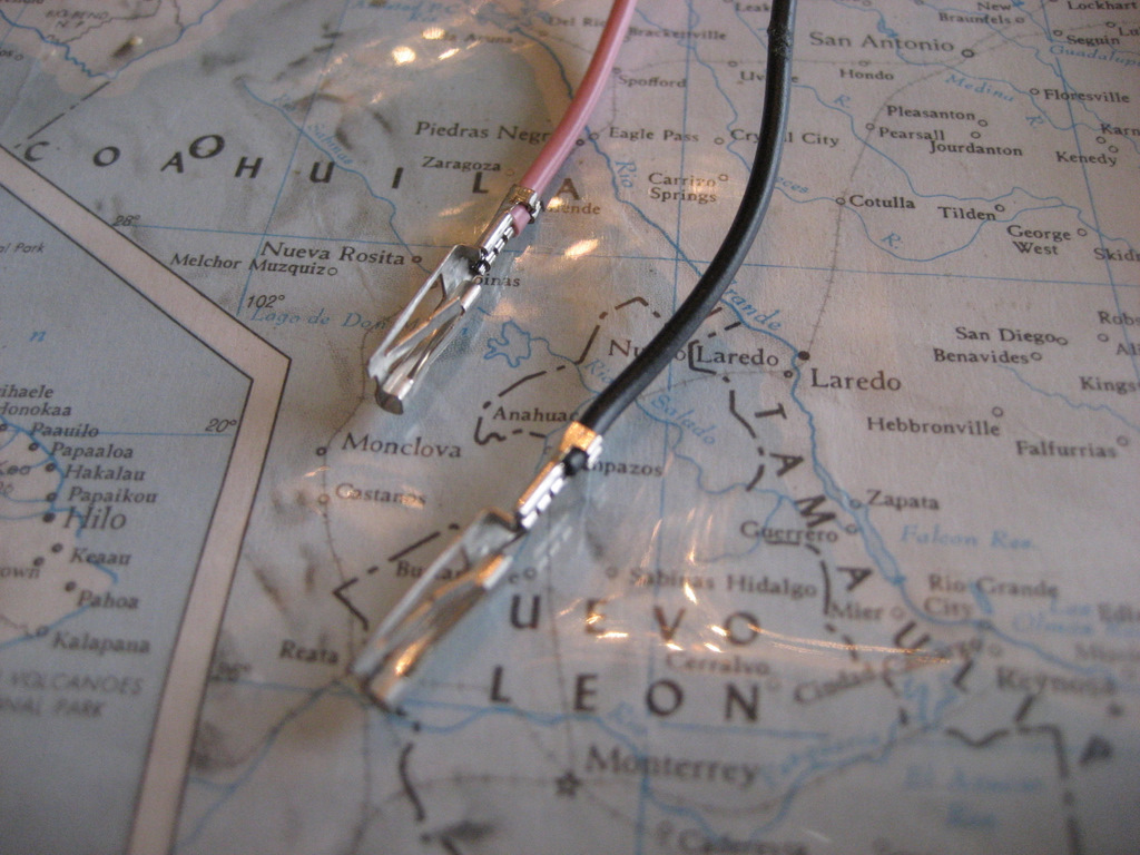
Insert these into the green
and black connectors in Positions A1 and A7, just like the originals:
Reinstall the TPAs:
Connect the two white
connectors together:
This provides a Ground and
Ignition connection to the new Nav Commander harness.
Closely examine what you
have done. BE SURE the pink and black wires are in the correct positions
in all of the connectors.
The pink wires must connect
with the pink wires and the black wires must connect with the black wires.
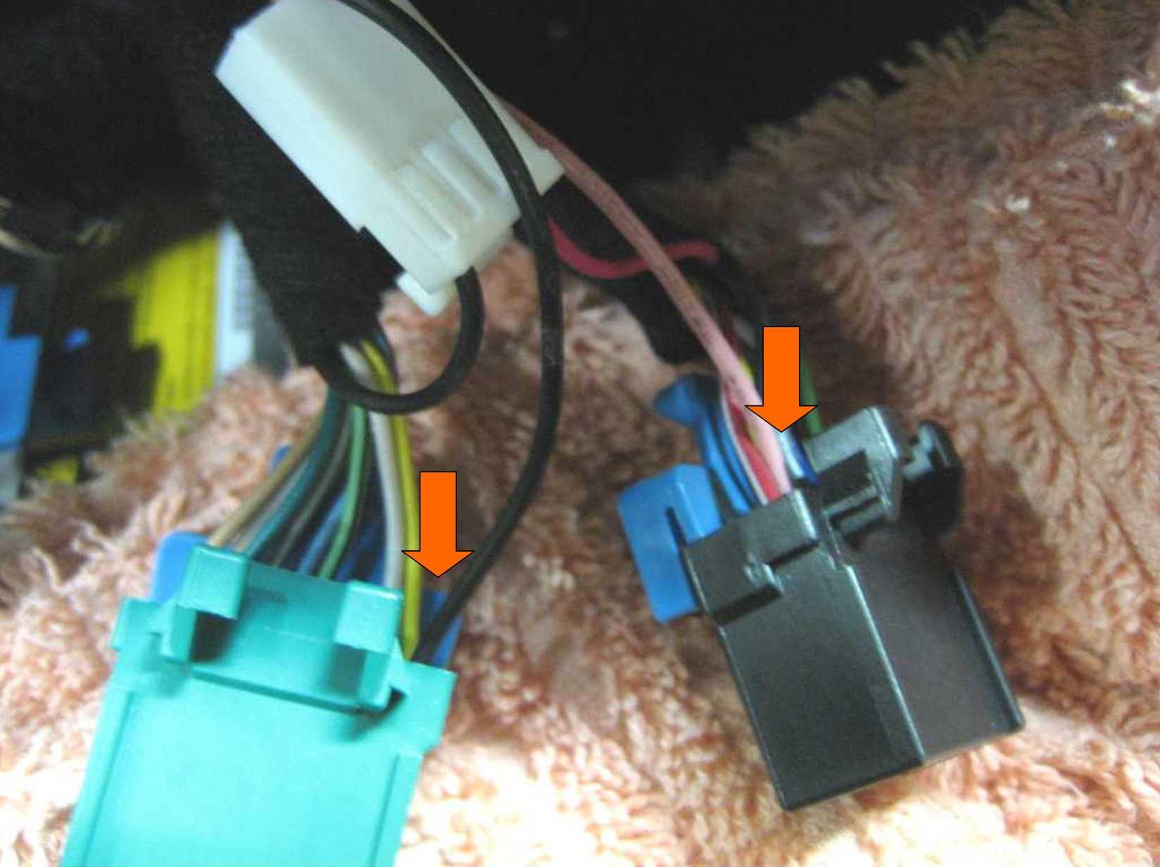
Plug the green and black
connectors back into the HVAC module:
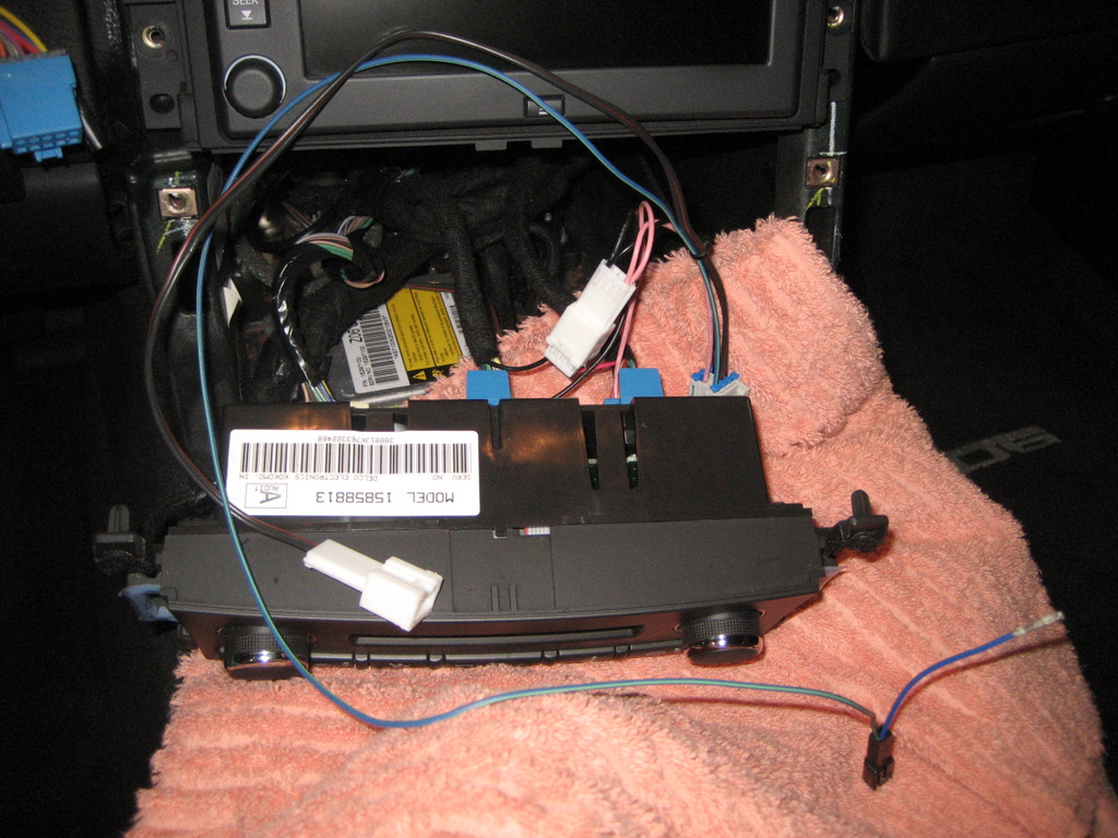
This leaves the remaining
white connector and the blue DIC wire to be connected.
Set a soft cloth over the
HVAC module and pull out the Nav Unit after removing the four 7mm screws.
Here's the back of the Nav
Unit:
Remove the 12 pin connector
by squeezing the tabs, just like you did with the green and black connectors on
the HVAC.
See the green/white wire
circled? Don't mix it up with the other green/white wire:
This time, remove the bottom
TPA so you can remove that wire and terminal:
This is the same Delphi
Micro Pack 100 terminal and connector series as the HVAC module connectors.
Remove the green/white wire
the same way as you removed the HVAC Ground and Ignition terminals:
Examine the speed sensor
connector with the new green/white wire:
Here is the new speed sensor
terminal:
Insert the original
green/white wire into the speed sensor connector:
Insert the new terminal in
the 12 position connector in the same location as the original connector:
Here is the new terminal
inserted:
Reinstall the TPA.
Here is the new connector
installed:
Push down all four locking
buttons.
Here is another view:
Next, examine the remaining
white connector on the harness:
Connect the two connectors
together:
and add a couple of tie
straps:
Plug the 12 pin connector
back into the Nav Unit:
OK, only one wire to go!
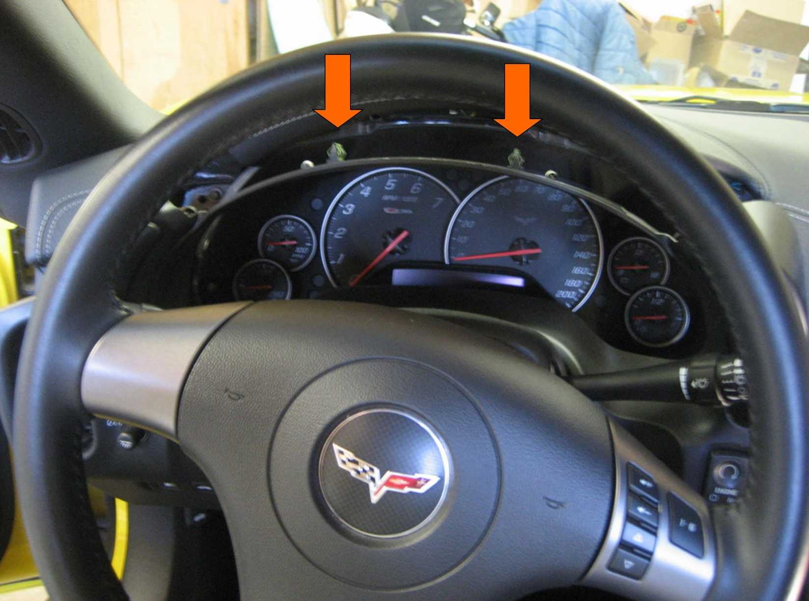
With the Nav Unit still
removed, pull out the Instrument Cluster Bezel.
It's usually easiest to grab
near the lower left and pull that section out first, but you can also grab the
top sections and pull.
The bezel is held in by
clips only, so just pull:
There are two smaller clips
near the top:
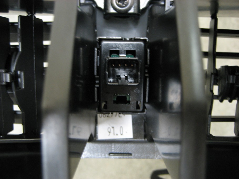
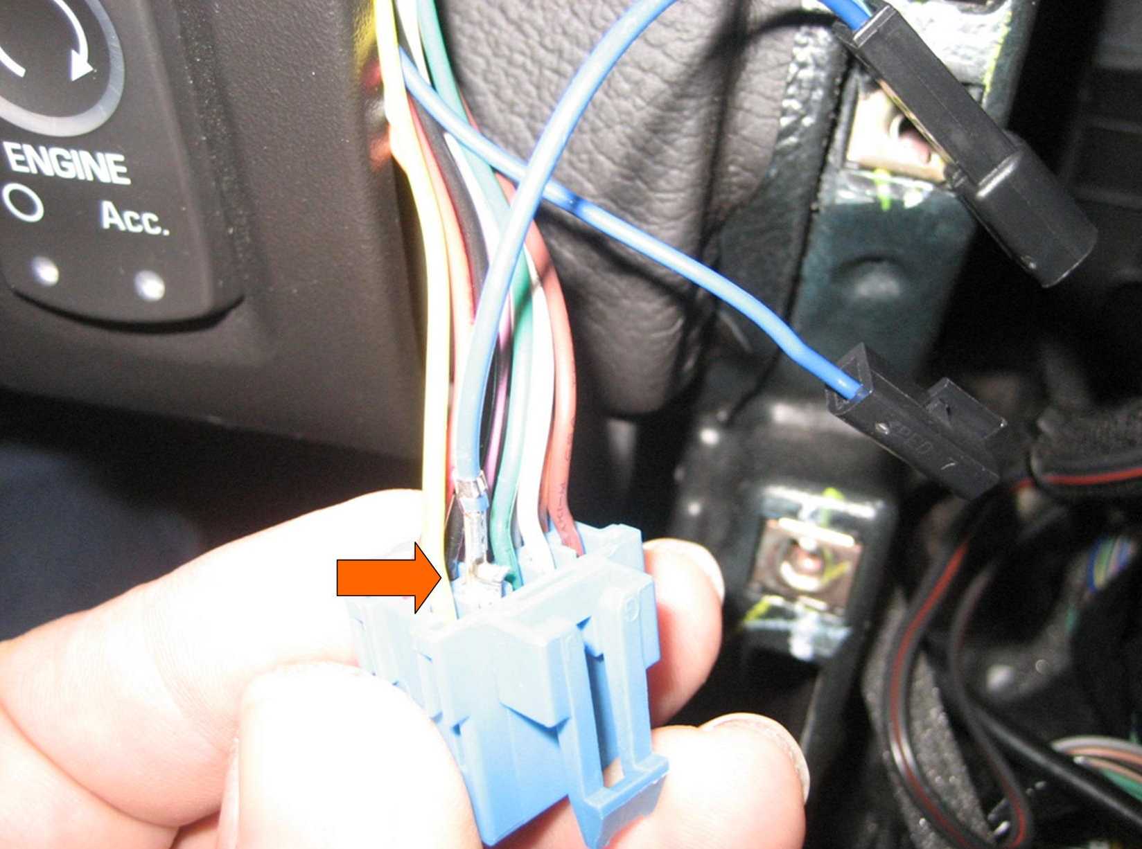
This is the Driver
Information Center (DIC) connector:
See the locking tab at the
bottom?
Here is the back of the DIC
switch assembly:
The locking tab clips onto
the part at the bottom:
To remove the connector, you
must push up to release the locking tab.
The problem is that you
can't get your finger in there to push up -
plus, you can't see back there
when you are behind the steering wheel.
So it's easiest just to
remove the switch from the bezel.
You can see two of the three
screws in the previous photo.
Here is another photo of all
three screws (top one sort of hidden):
With a short Phillips
screwdriver you can easily remove the DIC switch assembly from the bezel.
Then remove the connector
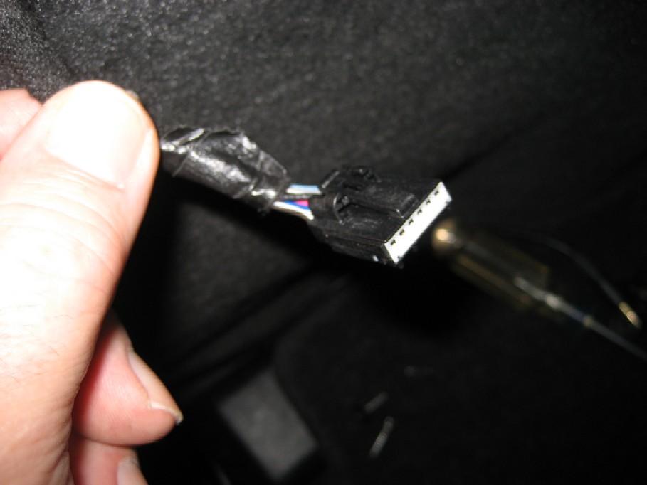
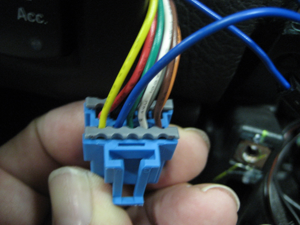
and reinstall the DIC switch in the bezel.
Here is the back of the DIC
connector:
See the blue wire in
Position J?
(By the way, the Service
Manual incorrectly shows completely different colors for these wires.)
We want to remove it.
So first you must remove the
TPA:
Here are the clips you push
to remove it:
You only need to remove the
TPA near the blue wire.
Once the TPA is removed, you
insert a very small screwdriver in the slot as shown here:
This will allow the terminal
tang to be released.
Here is a photo of the
terminal:
Once the tang is released,
the terminal will pull out easily:
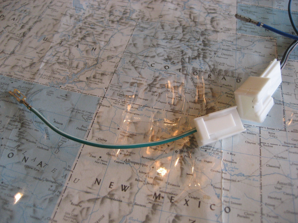
Here are the new DIC
connectors:
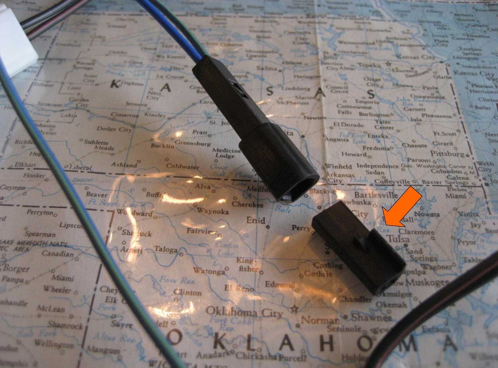
Install the single connector
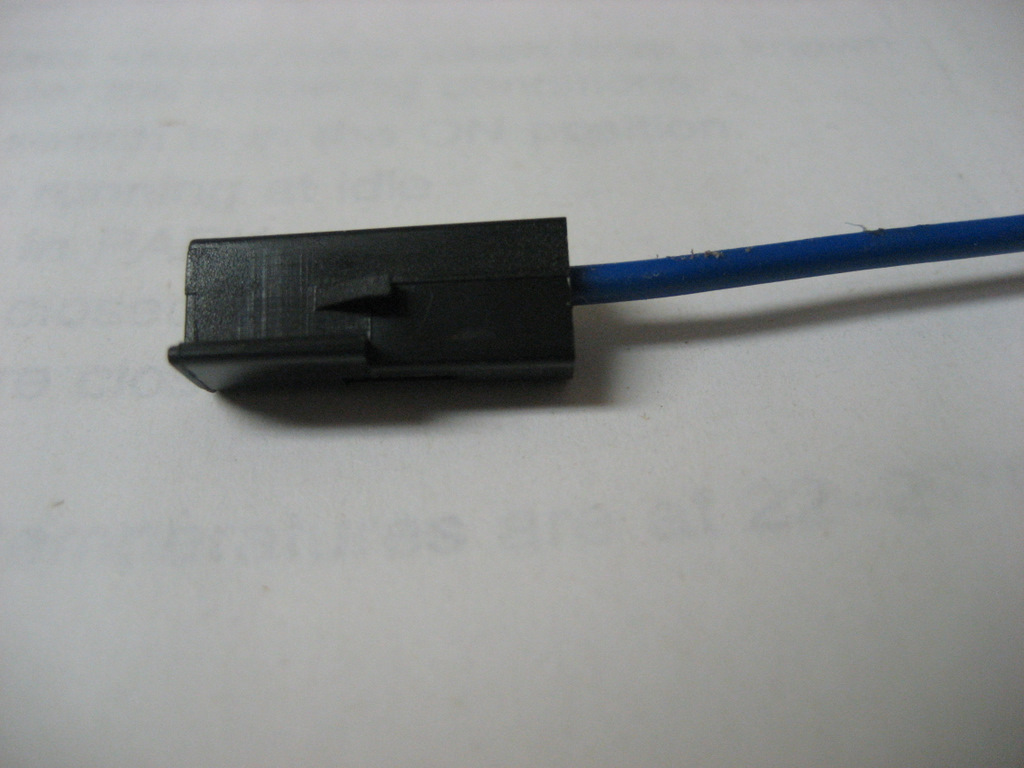
on the right onto the blue wire you removed from the DIC connector:
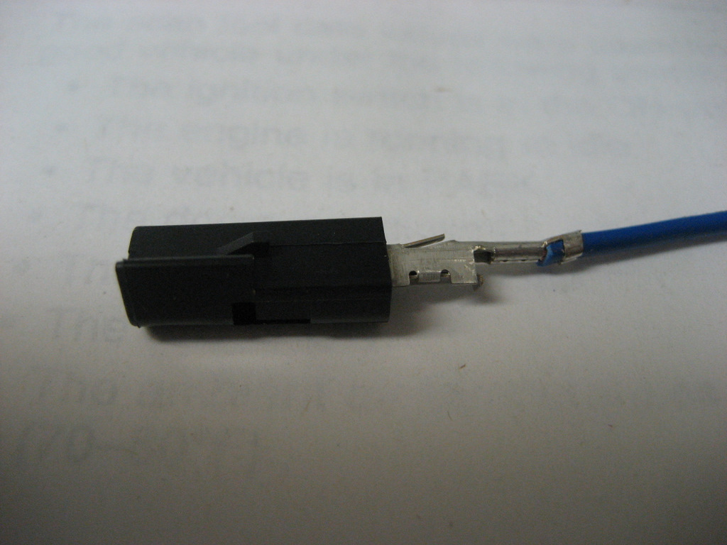
Here it is fully inserted:
Here is a photo of the new
DIC single connector:
Next, route the new DIC blue
wire from the harness behind the Nav Unit and into the instrument cluster
cavity.
Here is a photo of the new
connectors:
See the new DIC terminal on
the new blue wire in
the upper left?
Insert that wire and terminal back
into the DIC connector in Position J:
After it is fully inserted,
reinstall the DIC TPA:
Now connect the original DIC
blue wire with the connector on the harness:
Use a tie strap to make a
neat wire bundle, then plug the DIC connector back into the DIC switch.
Reinstall the Instrument
Cluster Bezel by pushing it in place.
The wiring connections are
now complete, except for plugging in the Nav Commander.
Reinstall the Nav Unit with
the four 7mm screws:
Reinstall the HVAC module
with the two 7mm screws.
(Push up on the HVAC module
as you tighten the screws to avoid later interference with the ash tray.)
Here is the Nav Commander
connector below the HVAC:
Here is how the Nav
Commander is connected:
Wrap the Nav Commander in
something soft to avoid rattles and connect it to the harness:
Push the Nav Commander back
under the HVAC unit far enough that the ash tray and cigarette lighter in the
console will clear it:
At this point, you might
want to try out the Nav Commander to make sure everything is working properly
before you reinstall the center console.
Take a slow drive, turn on
the Nav, and try to enter a destination.
You should see the
destination screen is blanked out whenever you are moving more than 5 mph.
As you are moving, push the
DIC TRIP button for a second or two.
This should bring the
Destination Screen to life, allowing you to enter destinations.
You have about 30 seconds or
so, then the screen will go blank again for a few seconds, then light up again
for you to continue.
When you are finished
entering your destination, again push the DIC TRIP button for a couple of
seconds to place the Nav Unit back in Normal position.
If you do not place the Nav
Unit back to Normal, it will not track properly and you lose the Time to
Destination function.
So always place it back
while driving.
Once you are satisfied with
the Nav Commander's operation, reinstall the center console.
You've finished!
Good luck on your
project!