C6 Corvette PAL Installation
(updated 8/25/23)
Introduction
This web page duplicates part of the installation shown in the PAL section of the following website:
with the addition of more details and alternative installation methods.
Click here for lots of Frequently Asked Questions about the PAL
The PAL installation instructions that are included with the PAL module and wiring harness are meant for a GM Technician. For the "do-it-yourselfer", part of the installation is difficult when compared to the installation of aftermarket Ipod adapters. This is mainly because of the splicing of a Class 2 Serial Data wire in a very inaccessible location. Some owners might want to consider the alternatives shown on this web page.
Five alternatives are shown, as follows (you can go directly to each alternative by clicking on them):
![]() DON'T DO IT "the GM way"!
DON'T DO IT "the GM way"!
See Alternative 5 instead!
3. Installation avoiding the Splice Pack area and instead connecting the XM wire at the XM receiver.
![]()
![]() 5. An ultra
simple PAL installation using a new custom wiring harness.
5. An ultra
simple PAL installation using a new custom wiring harness.
Note to owners: If you can offer any photos that will help in describing these alternatives, please email them to me and I will include them on this web page.
Thank you.
As an update, forum member John Beidl (jbeidl) offered a writeup and photos that will assist other owners in removing their center consoles and installing the PAL. Click on this link to access John's information:
http://www.kawal.net/PAL%20wire%20routing.htm
Per the PAL instructions (the GM way)
(Note: Much of this is duplicated from the web page noted at the top of the page)
The XM receiver (located above the left rear wheelwell in the coupes and Z06s and behind the waterfall in the convertibles) is connected to the Class 2 serial data bus via circuit 5781, a light blue wire in Pin 15 of the XM receiver 16 pin connector mentioned previously. When the PAL is installed, this circuit must be disconnected from the serial data bus and instead the XM receiver is reconnected to a new Class 2 circuit provided in the PAL wiring harness.
The PAL installation instructions direct you to disconnect the original circuit at a Splice Pack (SP205), which is very unfortunately located high up above the driver's dead pedal, a difficult location to get to unless you happen to be a midget! This is NOT a fun place to work however!
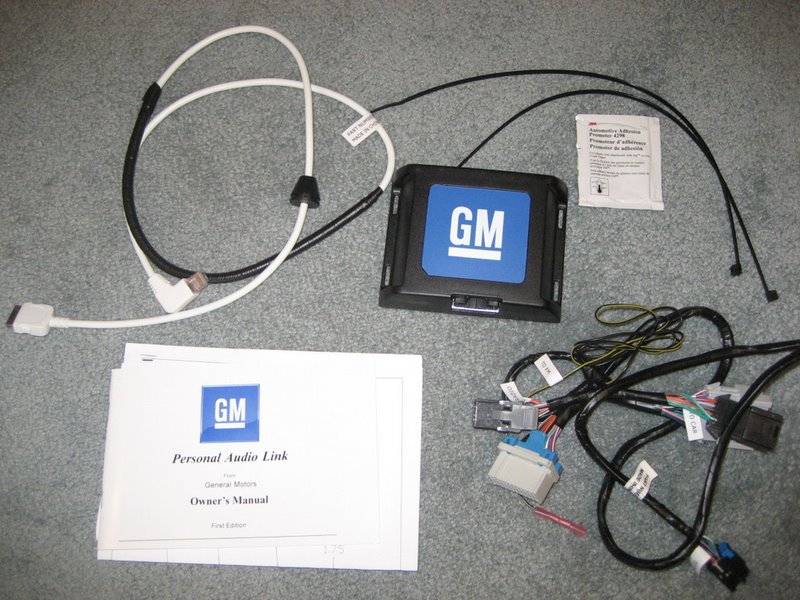
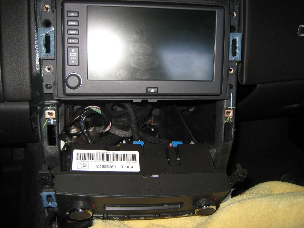
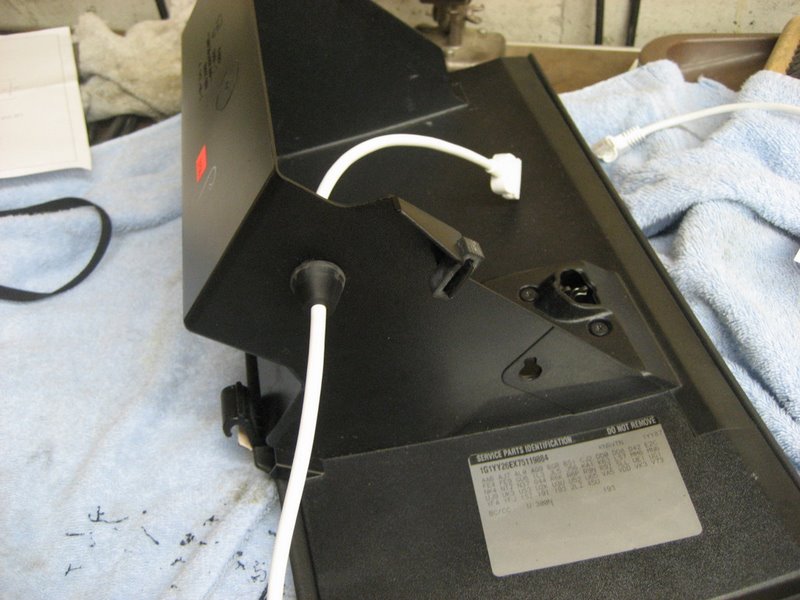
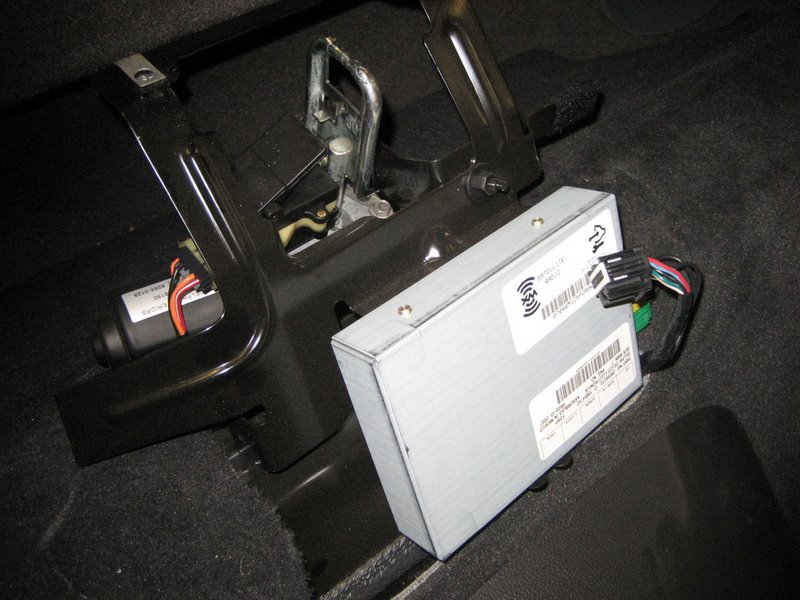
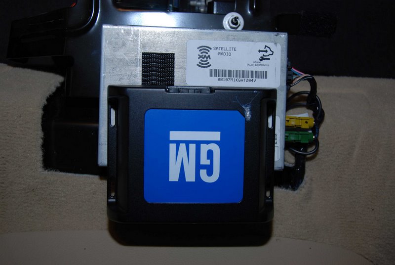
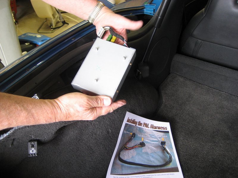
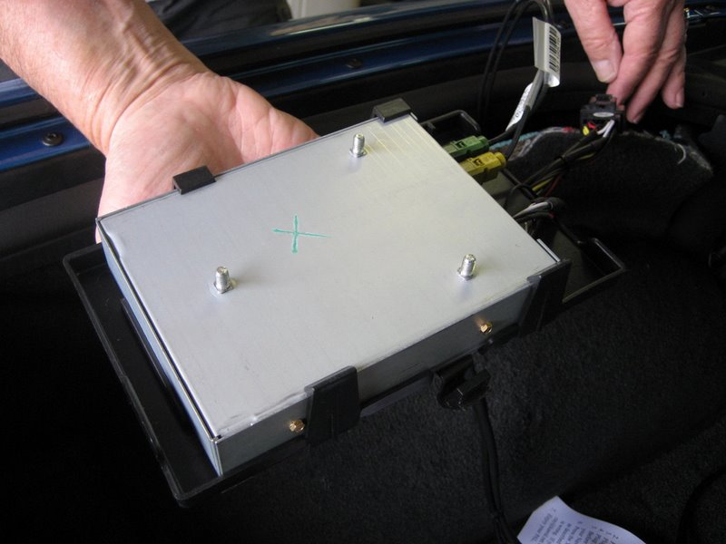
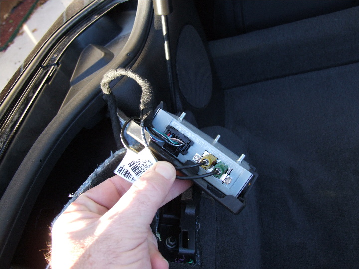
Here's what the entire package looks like:
As mentioned above, the PAL requires splicing into the factory wiring harness. It is only one wire, but it is the most difficult part of the entire installation. Let's start here, because the rest of the installation is similar to that of the Peripheral PXAMG.
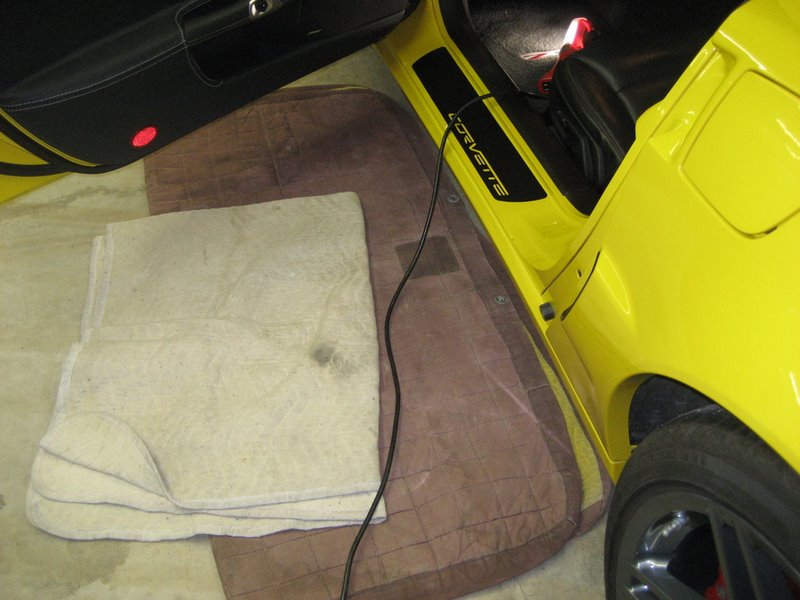
First get some padding, because you'll be on your knees for a while:
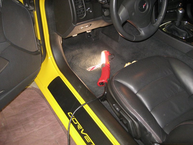
Next, you'll need a worklight to see under the dash:
The knee bolster, above your knees when you are sitting, must be removed. There are two Torx T15 screws holding it at the bottom:
But the knee bolster can't be removed until you first pull the instrument cluster bezel loose. If you have a telescopic steering wheel, move it all the way back. Then pull on the bezel towards you to unclip it:
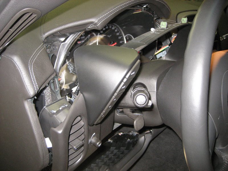
These clips on the back of the instrument cluster bezel prevent you from pulling the knee bolster out:
Once you pull out the cluster bezel a bit, the knee bolster can be removed:
Notice the wire on the far right and two on the left. These must be unplugged. Here is the far right one.
This is attached to the Radio Volume Compensation Microphone that is screwed to the knee bolster:
See the locking tab on the left?
Here are the other two connectors:
Here they are removed:
Here is the knee bolster removed:
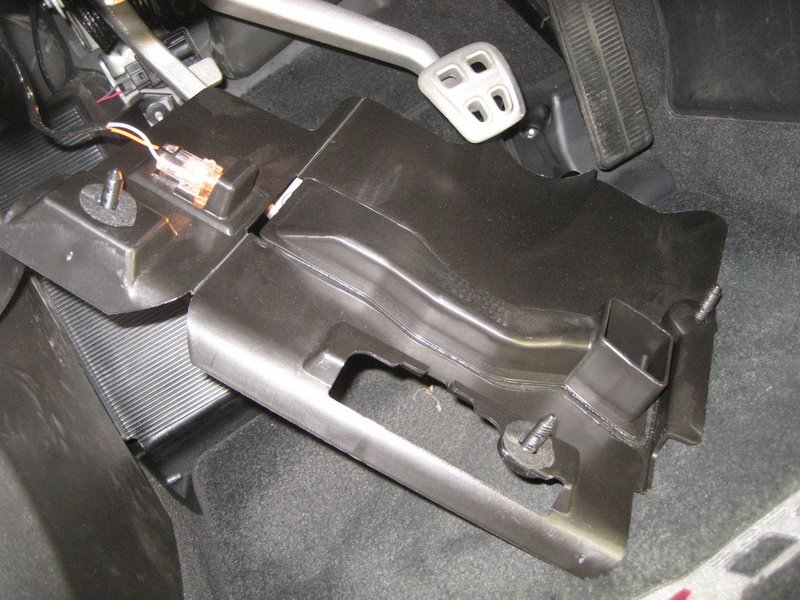
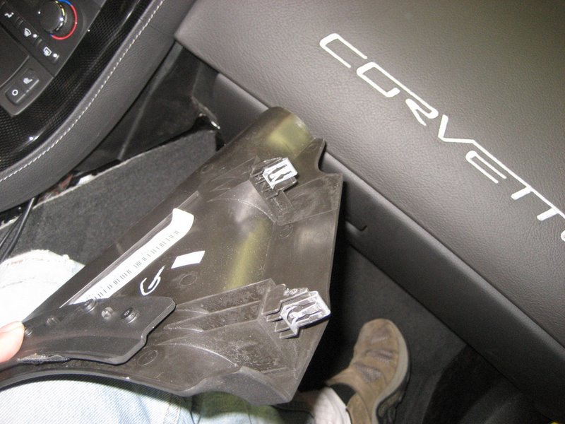
Next, this plastic panel must be removed. You can see two of the three round plastic clips holding it in place:
Here is another photo with one of the round clips:
Pull hard straight down and the panel can be removed:
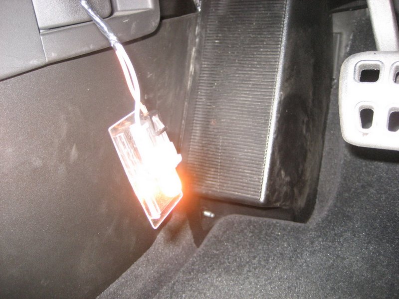
Unclip the lamp:
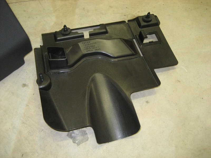
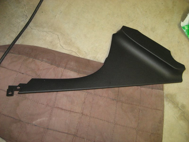
Here is the panel removed:
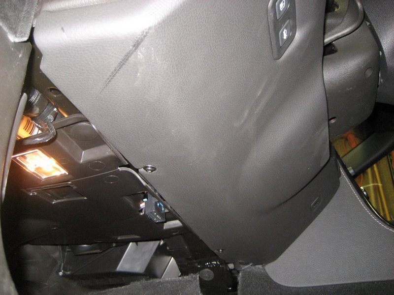
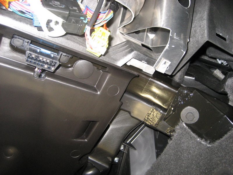
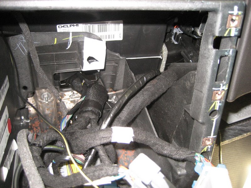
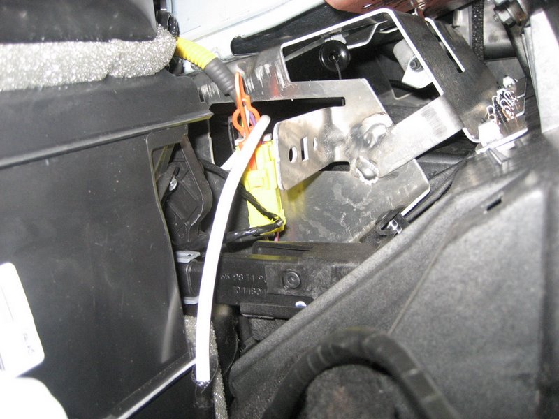
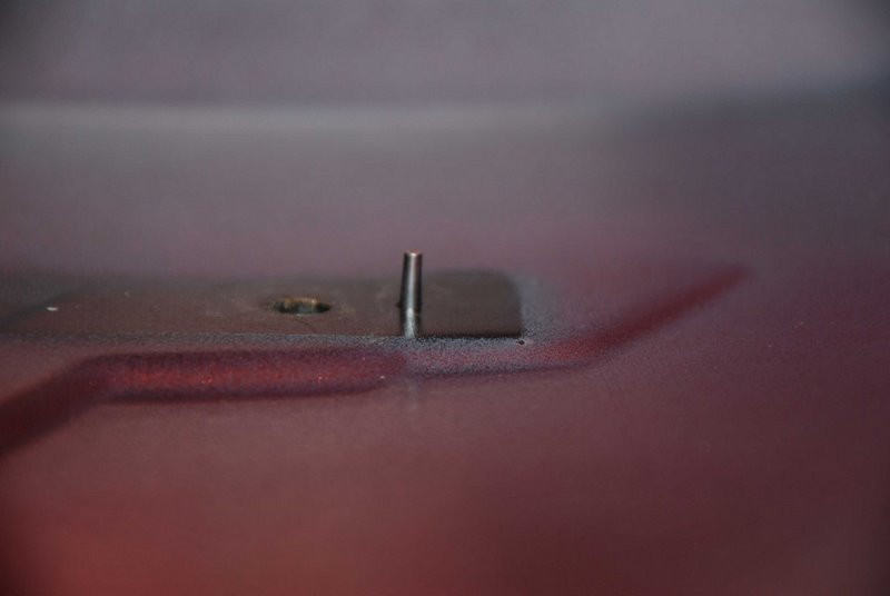
Next comes the hard part. Contort yourself under the dash and look high above the dead pedal. You'll see the Splice Pack taped to the wiring harness:
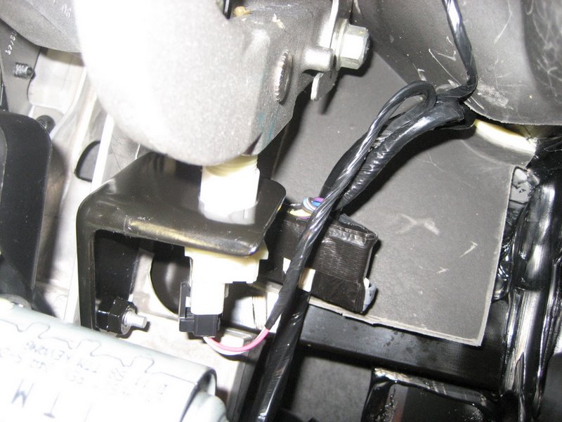
Pull it down away from the harness:
Pull it down as far as possible:
These photos may make it look easy, but reaching in there is WORK!, especially when you need two hands. Now, here's a controversial part of the instructions. The instructions direct you to remove terminal K connected to the light blue wire from the Splice Pack. Then you cut off the terminal from the light blue wire and connect the light blue wire to the wire from the PAL wiring harness. This disconnects the XM receiver serial data wire from the main bus and reconnects it to the PAL serial data wire. But why pull out the terminal? There is no real reason to, since all you do is throw it in the trash can. Instead, it makes more sense to simply cut off the light blue wire right at the terminal and leave the terminal installed in the Splice Pack.
For those of you who insist on the following the instructions, you will NOT have fun completing the following steps:
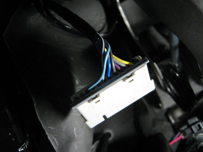
First, untape the Splice Pack:
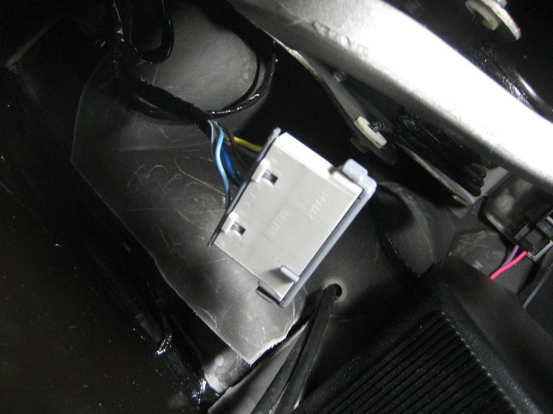
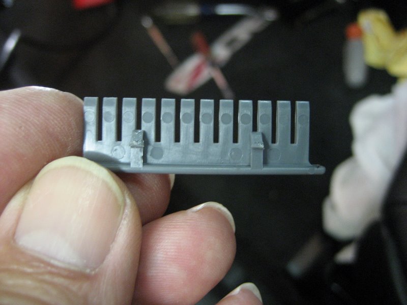
Next, pry out the comb (notice the light blue wire on the left):
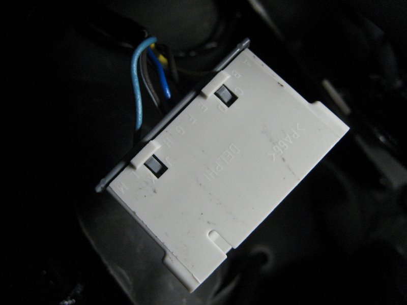
Here is the comb. All of the terminals connected to the wires into the Spice Pack connect to the comb and the main serial data bus:
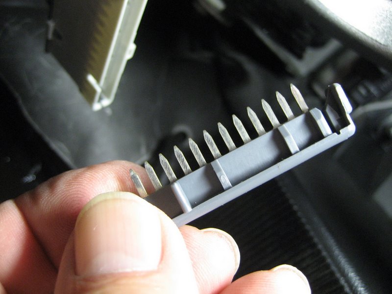
Next, you must remove the gray TPA (for
terminal protection assurance). The terminal will not come out unless you
remove the TPA
(unfortunately, the installation instructions do not explain this):
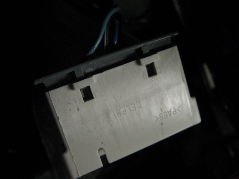
Pry it out with a small flat screwdriver. Do not try to unlock the two locking tabs - just pry out the TPA. Here it is removed:
Once the TPA is removed, pull hard on the light blue wire and it will come out of the Splice Pack:

At this point, you must reinstall the TPA and the comb, then tape up the Splice Pack as before. These steps disconnected the XM receiver Circuit 5781 from the main data bus. While the above photos may make it look easy, getting under the dash and actually doing it will have you grunting a lot! Instead, it would be far simpler to leave the terminal connected to the splice pack comb and just cut off the light blue wire. You could add a bit of electrical tape over the cut off wire, but otherwise you could have left the Splice Pack all taped up without ever pulling it apart. You still have to connect the light blue wire to the PAL harness wire anyway.
Whether or not you choose to remove the terminal from the Splice Pack, you end up with the light blue wire. Cut off the terminal and toss it. You now have the bare end of the light blue wire to connect to the PAL harness wire.
Next, let's get to the installation of the PAL wiring harness. Like the Peripheral PXAMG, you must remove the Nav unit to make the connections. So the center console must be removed. This isn't difficult, but it does take some time and patience.
I'll repeat some of the steps shown in the Peripheral PXAMG installation, since they are basically the same.
Here are the tools you need:
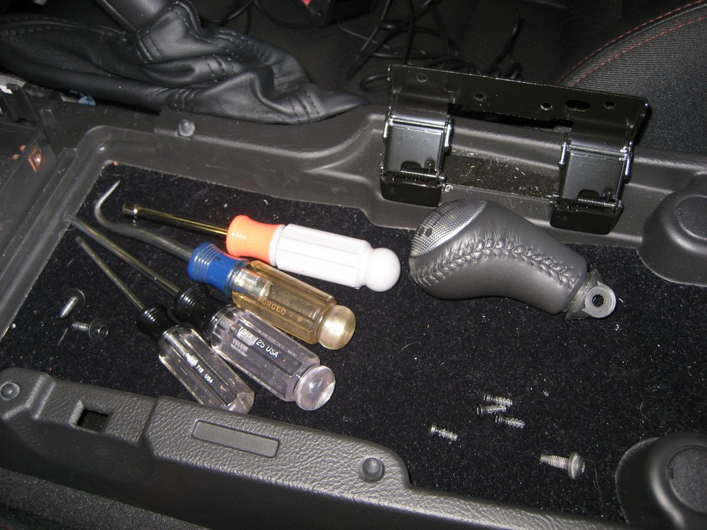
First use the T15 Torx driver to remove the four screws shown above to allow the console lid to be removed. Use the T25 Torx driver to remove the shifter knob (if you have a manual transmission). If you have an A6, you do not need to remove the shift lever, but you must move the shifter out of PARK toward the rear of the car. Press the Ignition Switch to Accessory to move it and you get to listen to the dinging for a while. As a caution, if you are not on level ground, chock the wheels or set the ebrake.
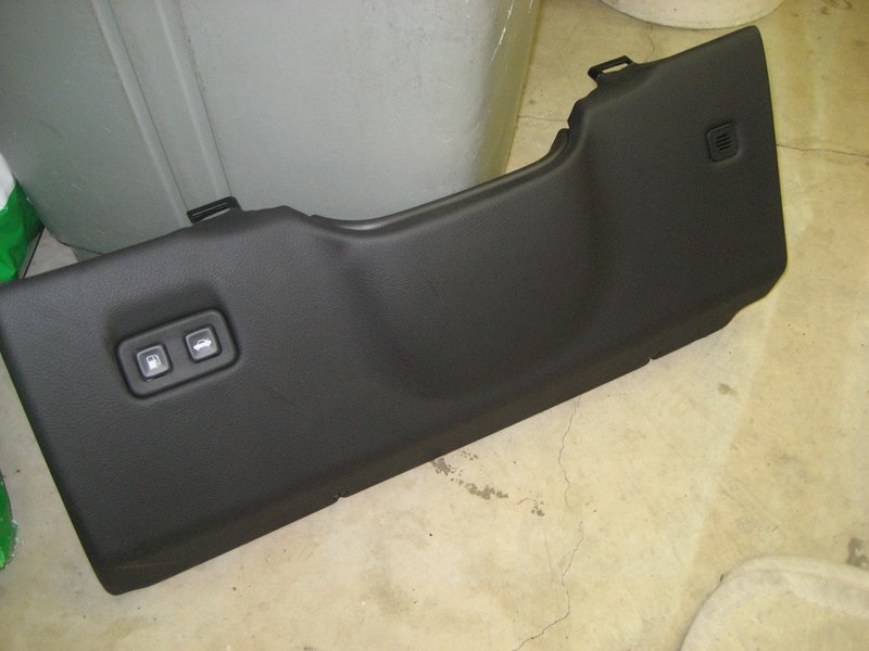
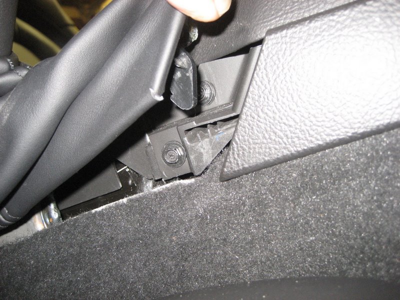
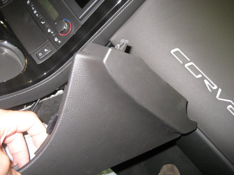
Use the 7mm nut driver to remove the two 7mm screws from the right side of the console - these are accessible by lifting up on the e-brake boot on the right. When you remove these two screws, you can then remove the right console trim plate by pulling down at the rear.
Next remove the two 7mm screws at the rear of the center console.
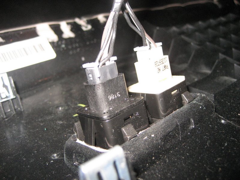
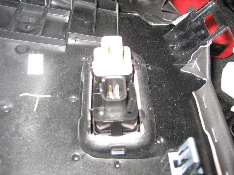
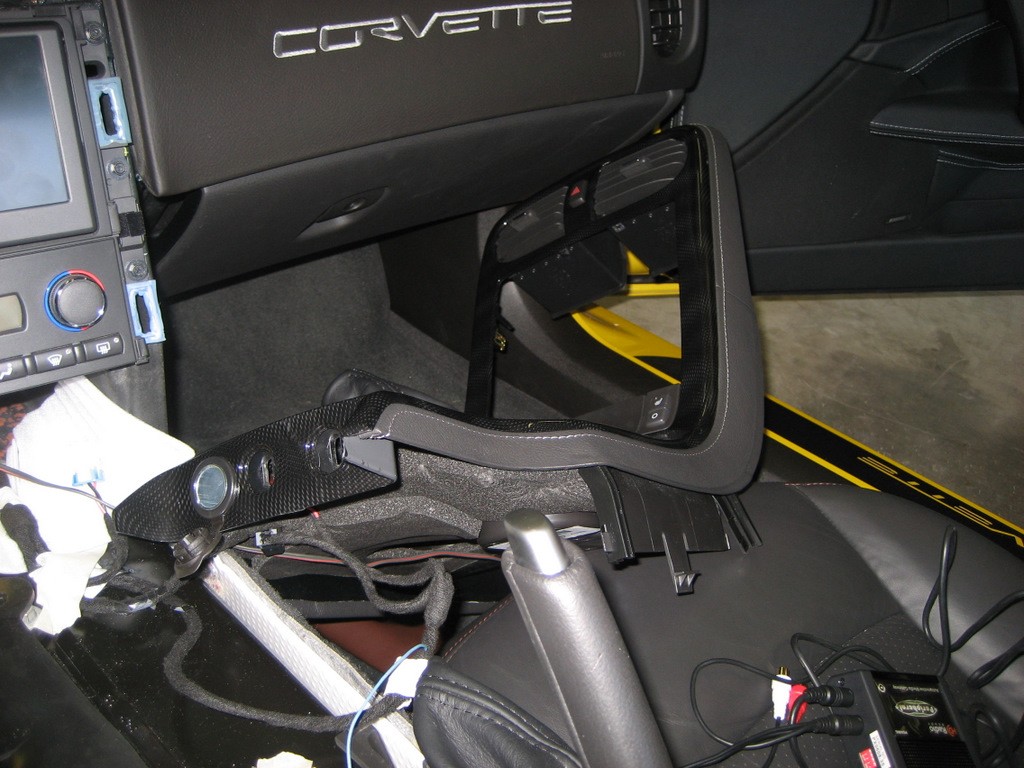
Lift up on the rear of the center console and it will come loose from the dash. Pull the shift lever back to allow the console to clear the shift lever (manual or automatic). At this point the only thing preventing removal of the console is the wiring. This is the tricky part. First pull the connector at the hazard warning switch near the top. Then pull the seat heater switch connectors (if you have them). Finally, pull the connector at the traction control switch - on this one, you lift a retaining tab rather than push the tab. The hardest connector to pull, if you haven't done it before, is the power plug (cigarette lighter) connectors. On these you must push a tab to release the connector - sometimes the tab is at the top, sometimes at the bottom. In the photo above, the bent awl works well for pushing the release tab.
You don't have to remove all of the plugs if you can manuever the console onto the passenger seat with part of the wiring harness still attached. Once you know how, it is a bit easier just to remove the whole thing and get it out of your way.
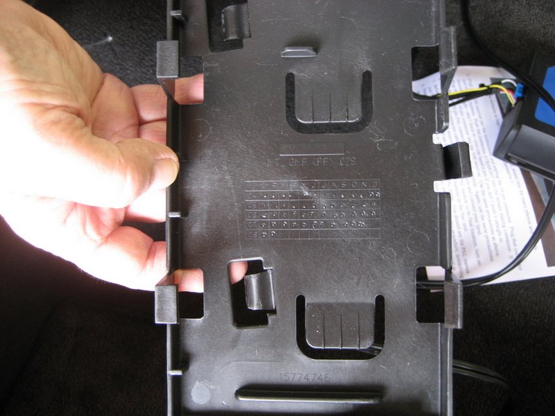
With the console removed, here is what it looks like:
This may look daunting, but it is quite easy to pull the console once the connectors are removed.
Here is the console sitting on the passenger seat:
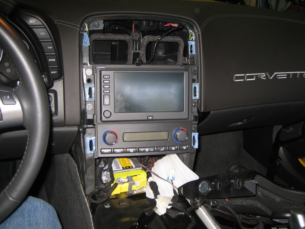
In the next photo, you can see the six 7mm screws removed that hold the HVAC controls and the nav radio in place:

A soft towel laying on the shift lever protects the units from being scratched when you remove them.
First, pull out the HVAC module:
It comes right out once the two screws are removed.
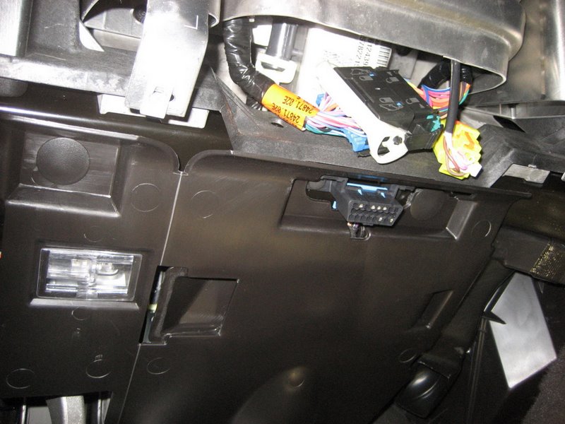
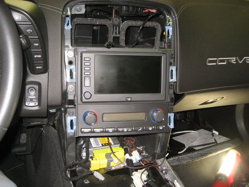
Next, pull out the nav radio unit and you'll see the two plugs in back:
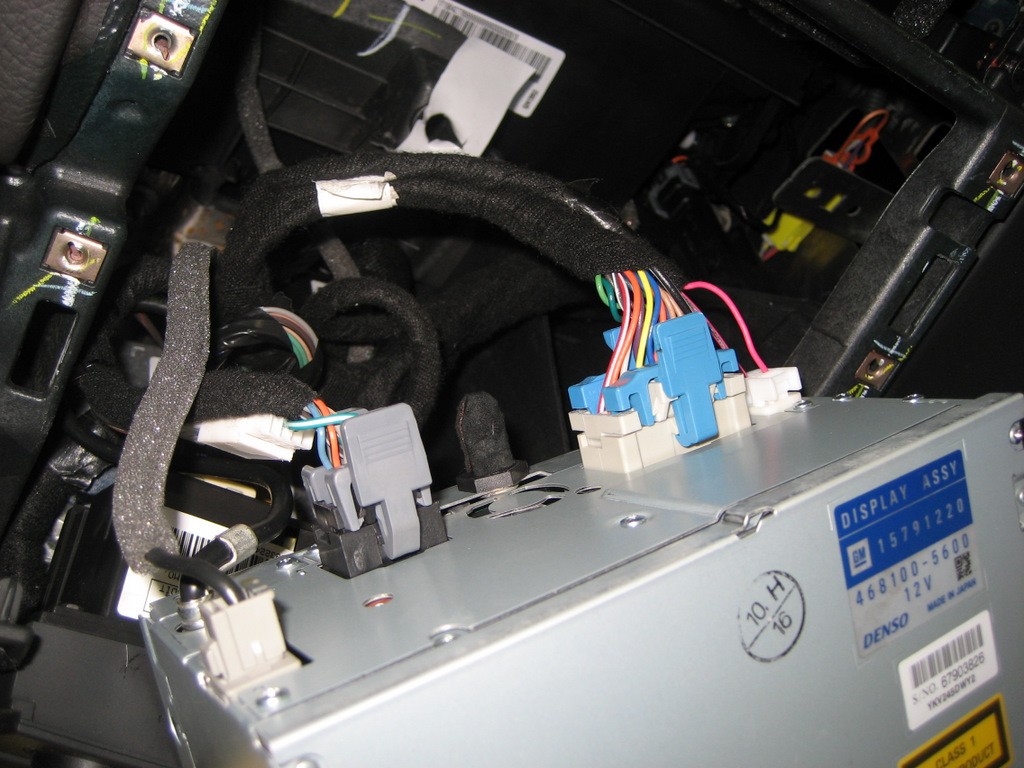
Here's another photo from the rear:
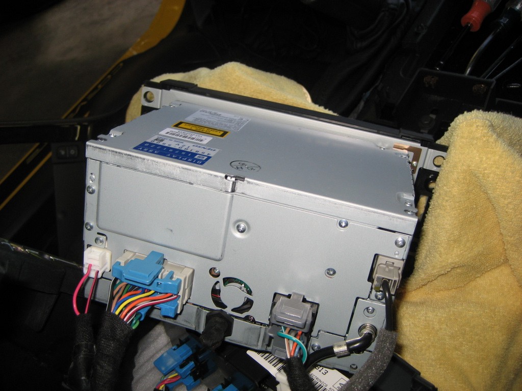
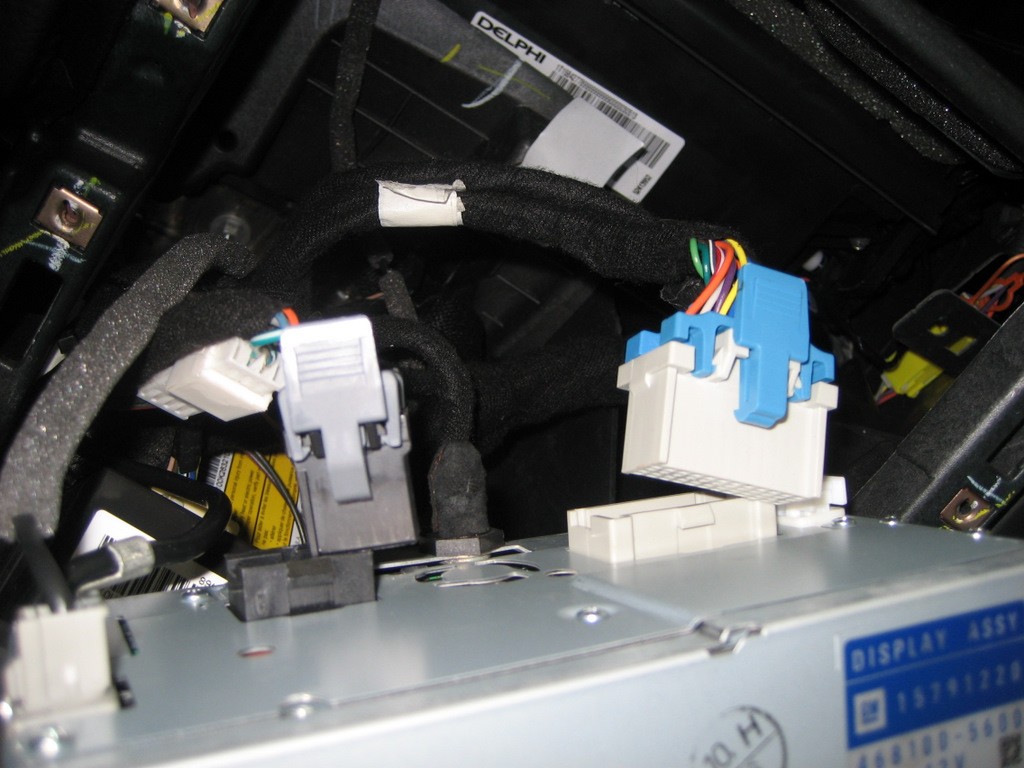
Both the 24 pin plug on the left and the 12 pin plug on the right must be pulled.
Simply push down on the tabs and pull:
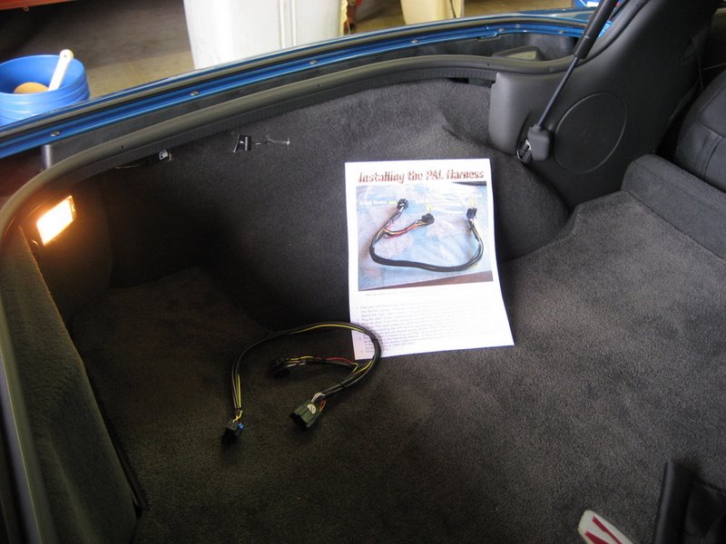
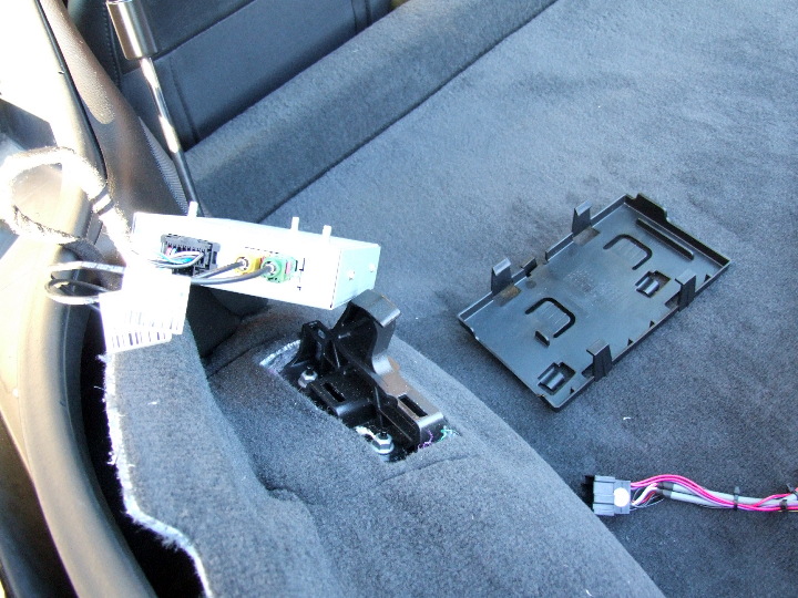
Next, plug in the PAL wiring harness:
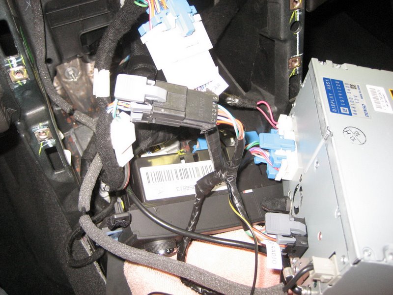
Route the single Class 2 Data wire as shown in the instructions and the remainder of the harness with the 16 pin connector down behind the Nav unit and out the right side of the console:
At this point, you need to decide where you want to locate your Ipod. Since you won't have control over the Ipod when it is plugged in, the glove box probably makes the most sense. And this is what the installation instructions direct you to do. So the following steps should be taken for a glove box installation.
Do not reinstall the Nav unit at this time because you will need access to the center cavity to route the Ipod cable from the glove box.
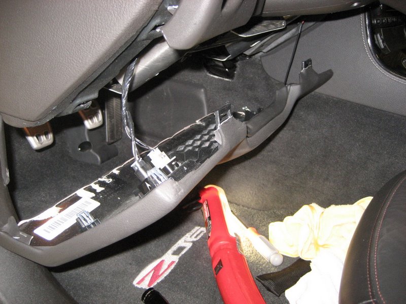
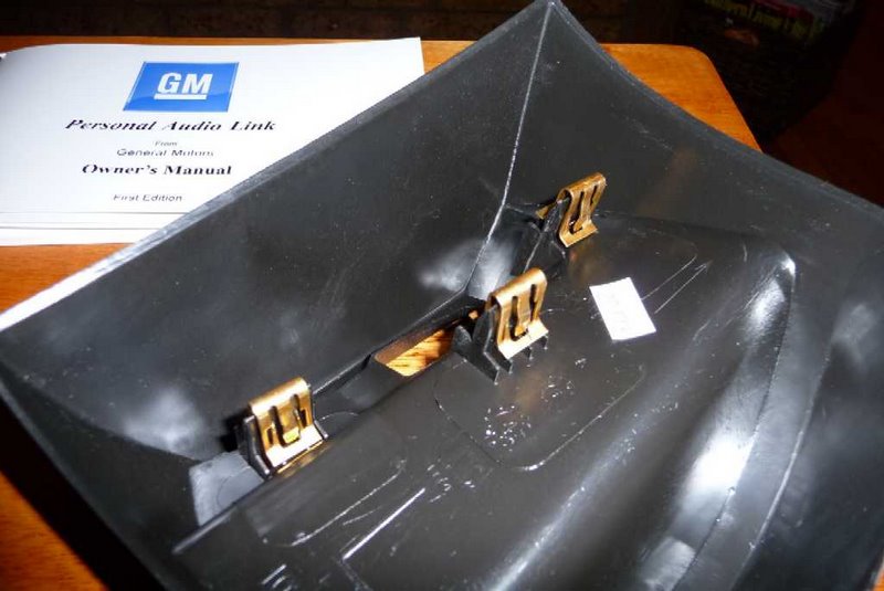
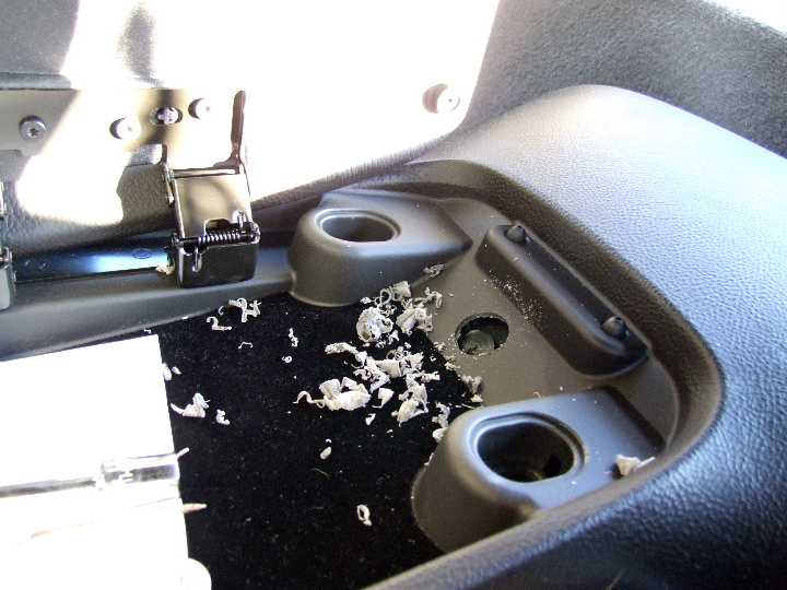
The installation instructions direct you to remove the glove box, but if you haven't done it before, the following photos may help. The glove box is hinged to the instrument panel on three pins (shown in the center of the photo):
These tabs latch onto the pins:
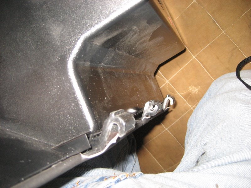
First push up on the right side to release the right tab from its pin. Then push up on the left side to release that tab. Then pull down to release the center tab and the glove box will come out. You will need the glove box out to modify it for the Ipod cable.
Notice the supplied template is different from the one in the instructions:
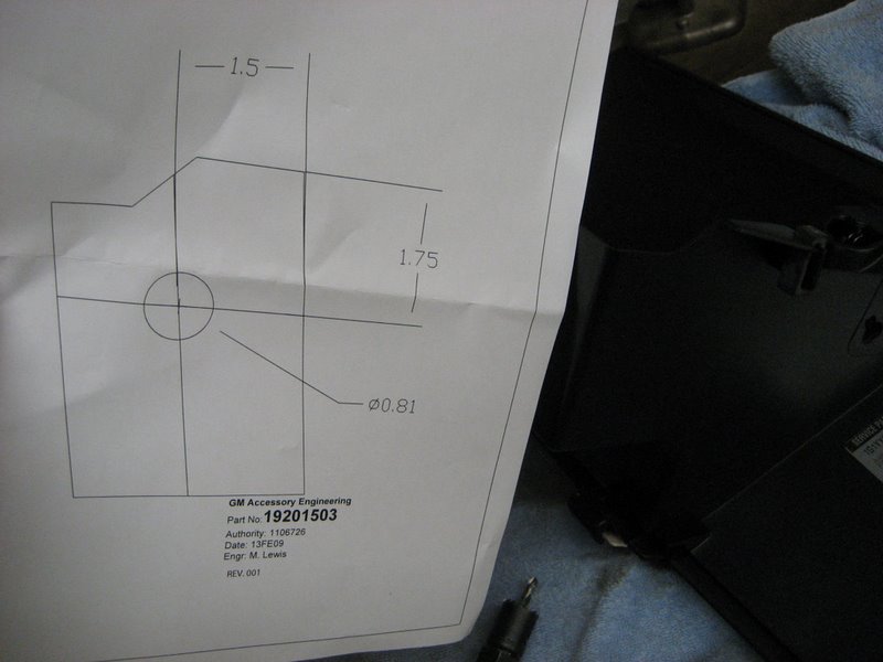
Hold it up against the side of the glove box to see where the hole goes:
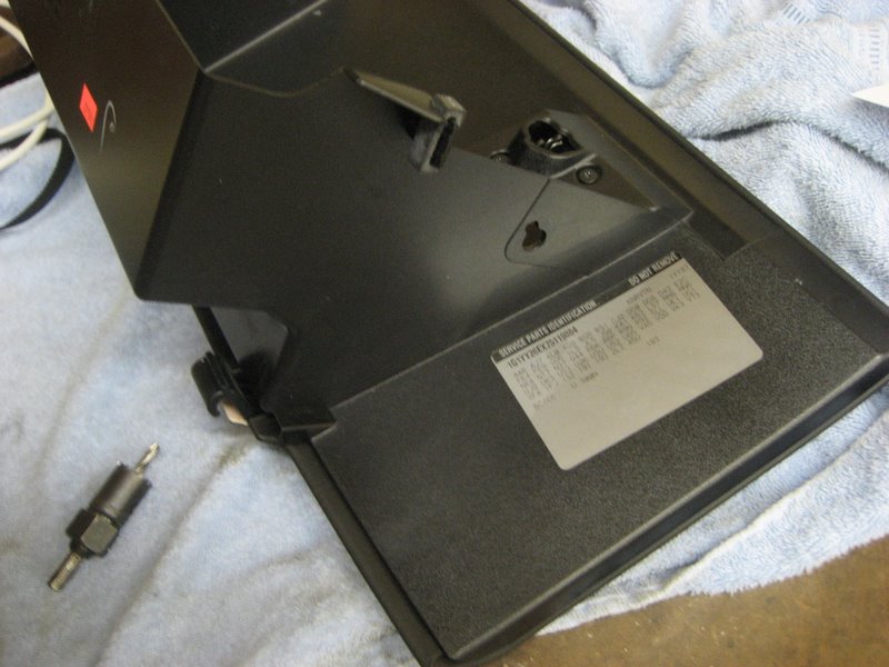
Drill a 13/16" hole here:
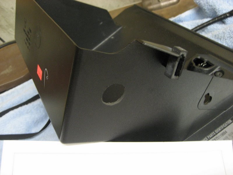
And push the Ipod cable in place:
Next, route the cable through the instrument panel:
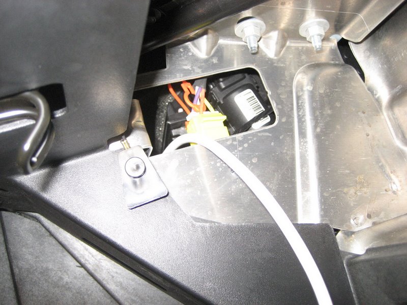
Here, the taped section is pulled through and routed down alongside the cable with the 16 pin connector:
Pull both cables out at this location:

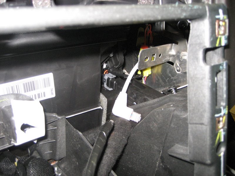
Reinstall the glove box with the Ipod cable routed through here:
Another view also showing the second cable with the 16 pin connector:
Here are both cables pulled through:
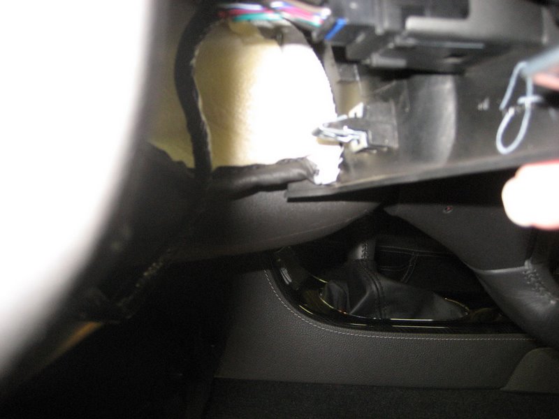
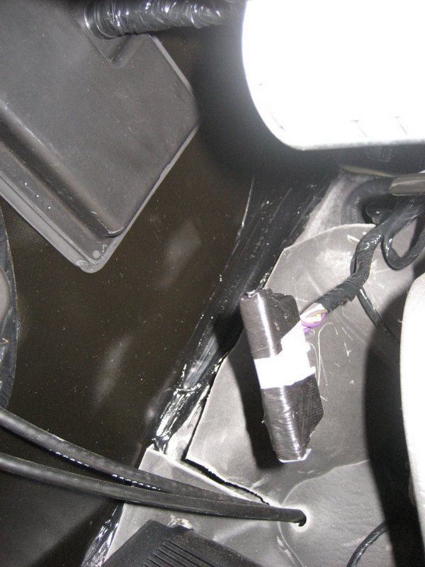
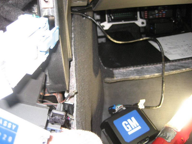
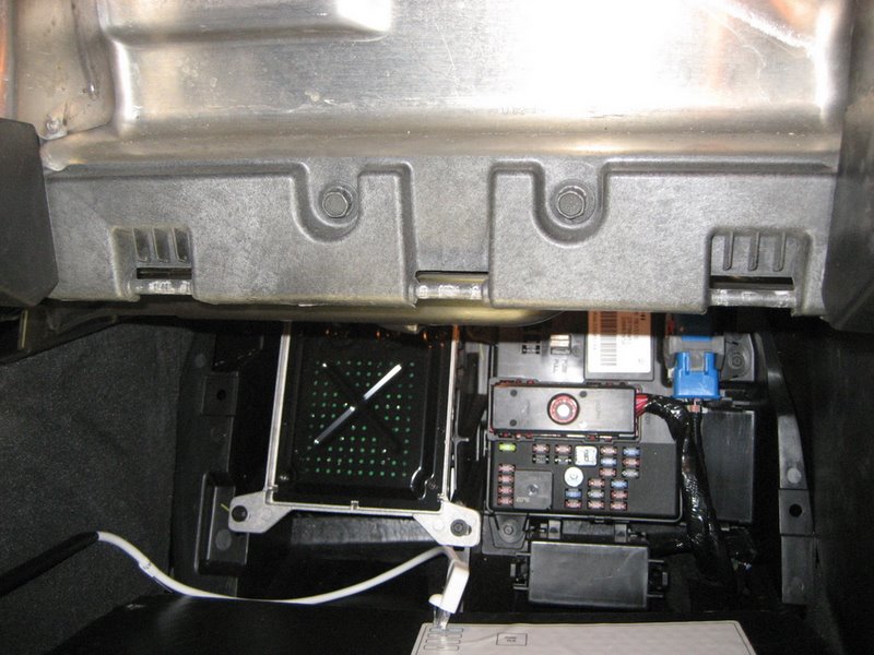
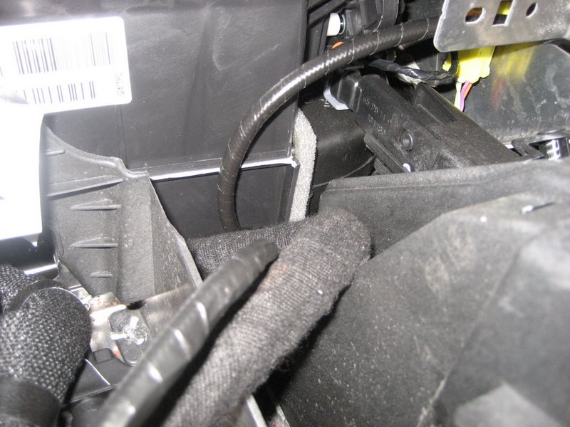
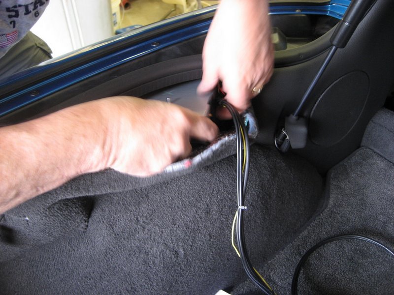
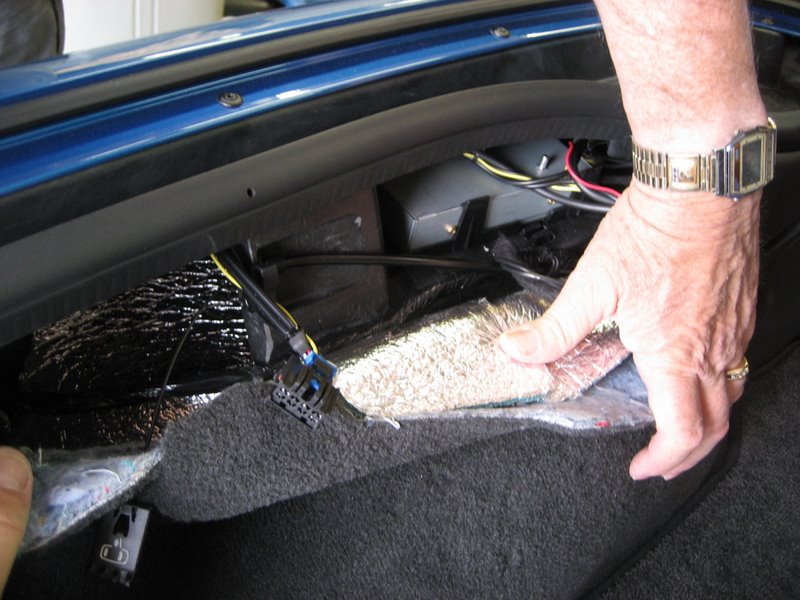
Pull back the side carpet and route them under the foam block:
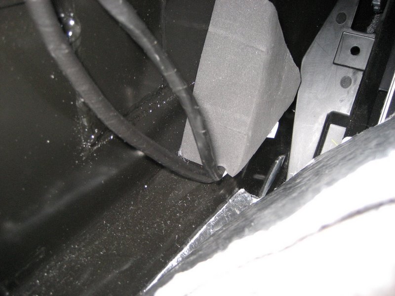
Fish them back under and behind the electrical panel (it isn't easy!):
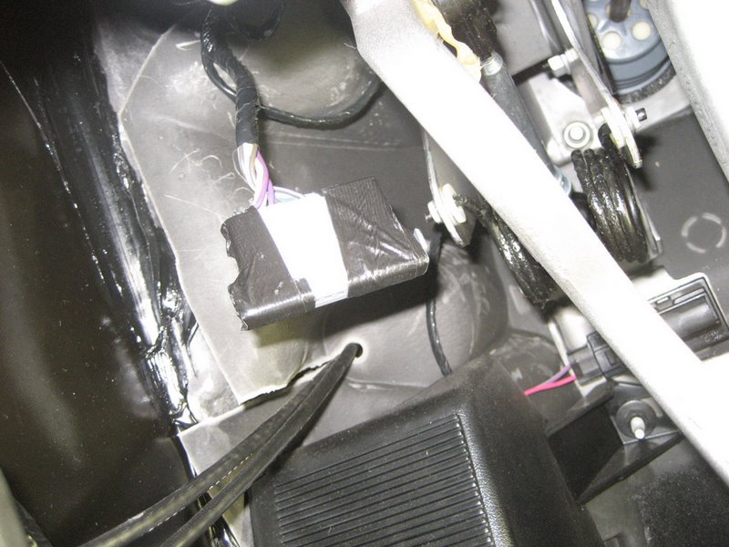
Finally, plug them into the PAL module and stick the module in place:
Now that all of the module wiring is done, you can finally reinstall the Nav unit. Making sure the connectors don't get crunched, push the Nav unit back in place and loosely screw in the four 7mm screws holding it in place. Also reinstall the heater controls:
As a hint, before tightening the six screws holding the Nav unit and heater controls in place, push up hard to take any slack out of the screw holes. I found if you do not, sometimes the ash tray will very slightly contact the bottom of the heater controls and not close perfectly.
At this point, most of the hard work is done. You route the Class 2 data wire under the dash to the light blue wire and connect it using the crimp connector.
Reinstall the underdash panel, the knee bolster, and the instrument cluster bezel.
Enjoy the PAL.
Per the PAL instructions, but without cutting the Pin K terminal
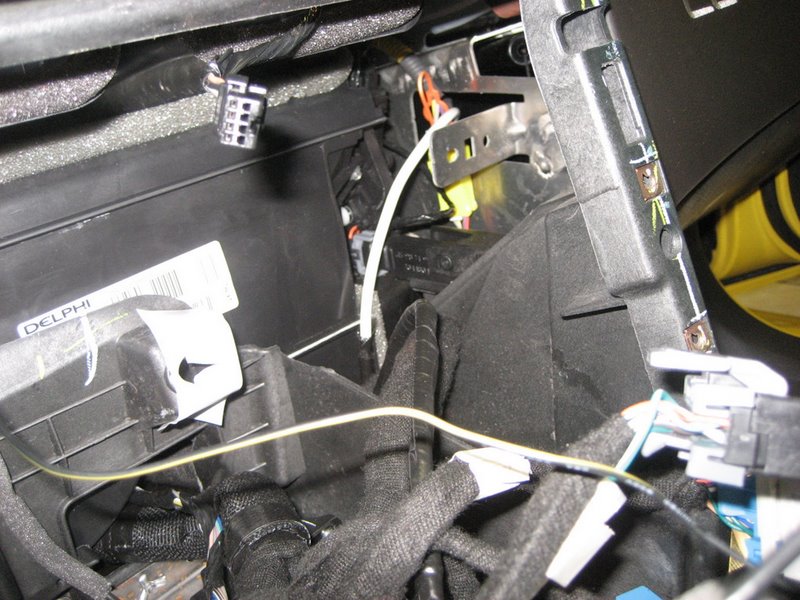
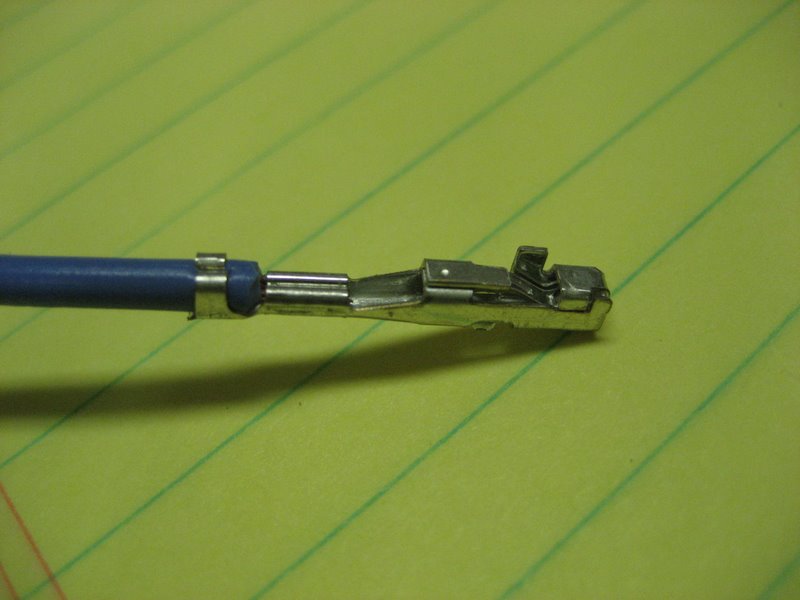
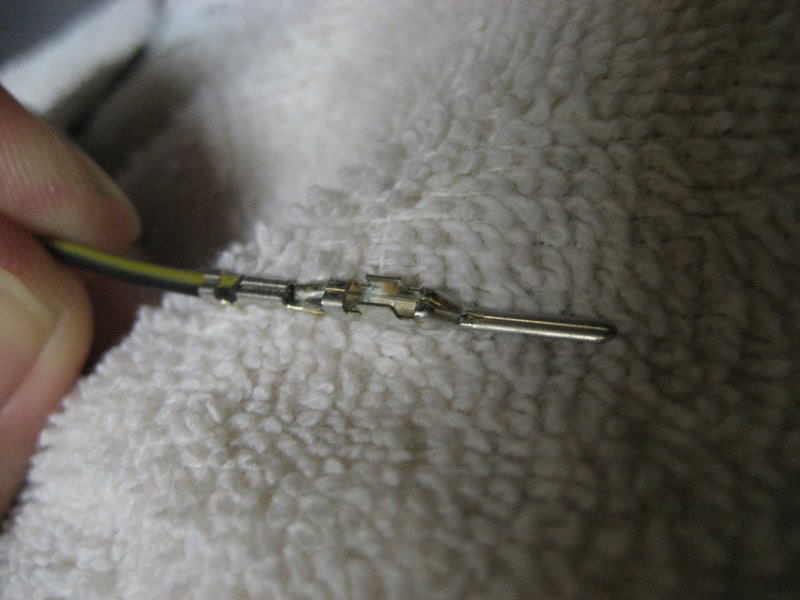
If you elected to pull the Pin K terminal rather than simply cutting it off and splicing the XM wire from the PAL harness, here is what you have:
The above terminal is part of the Delphi GT 150 connector system.
The terminal part number is a 12191812. Its mating male terminal is a 15304702.
Rather than cutting off this female terminal, you can crimp a male terminal to the XM wire from the PAL harness and, using GT 150 connectors, you can avoid cutting into the factory wiring harness. If you elect to go this route, reinstall the comb and TPA into the Splice Pack and tape it back up.
You will need a male and female connector into which you will install the terminals. Delphi does not offer a single place connector (for one terminal) but they do have a 2 cavity connector set that will accept these terminals. The part number for the female connector is a 15332129 and its male counterpart is a 15332130.
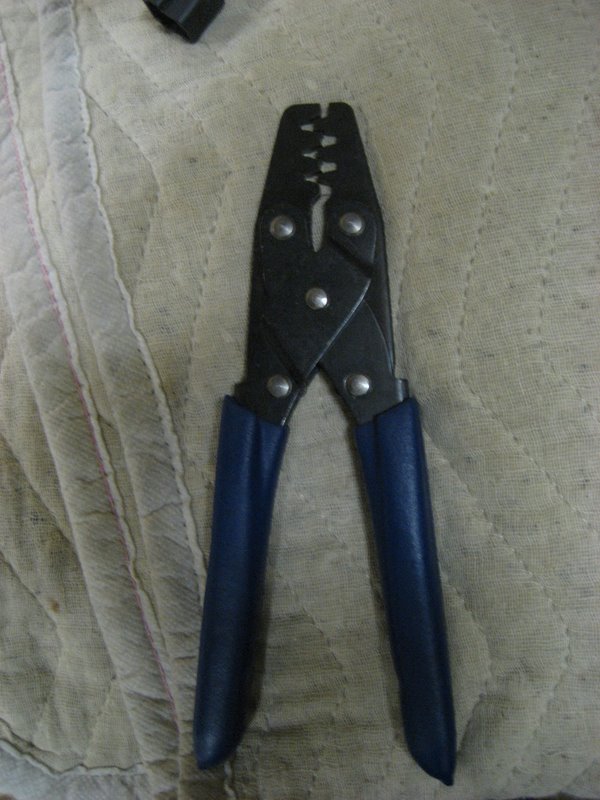
You will also need a wire crimper suitable for these terminals. I found the Tool-01000 from Ballenger Motorsports works well. Here is their link:
It's about $30.
Here's a closeup of the female terminal 12191812:
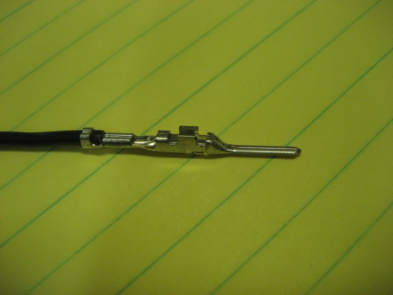
Here's the male terminal 15304702:
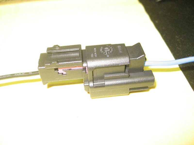
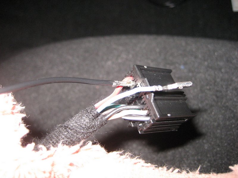
Here are the male and female connectors.
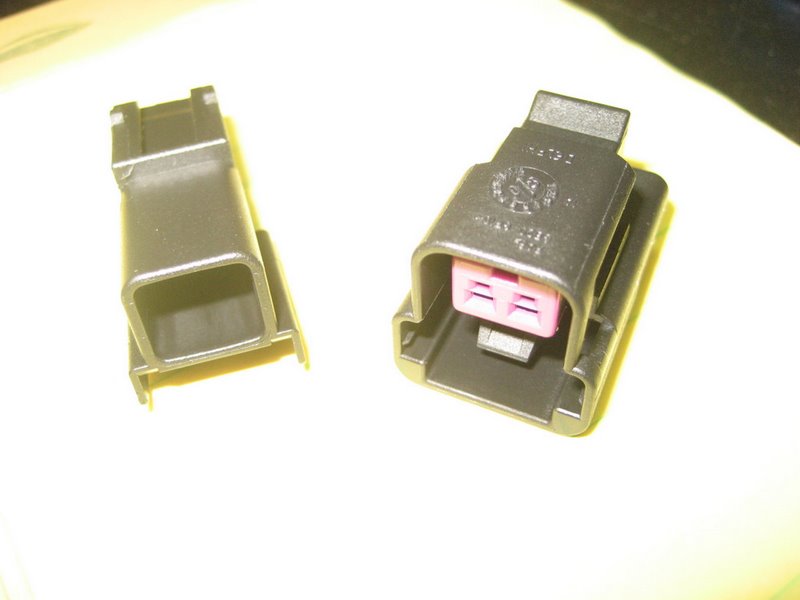
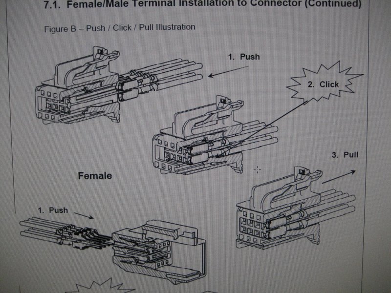
These connectors have a Side Lock Cover (pink) that provides a secondary locking mechanism for the terminal. Here, the female terminal is being pushed into the female connector. Once it clicks in, you push the Side Lock Cover in its locking position:
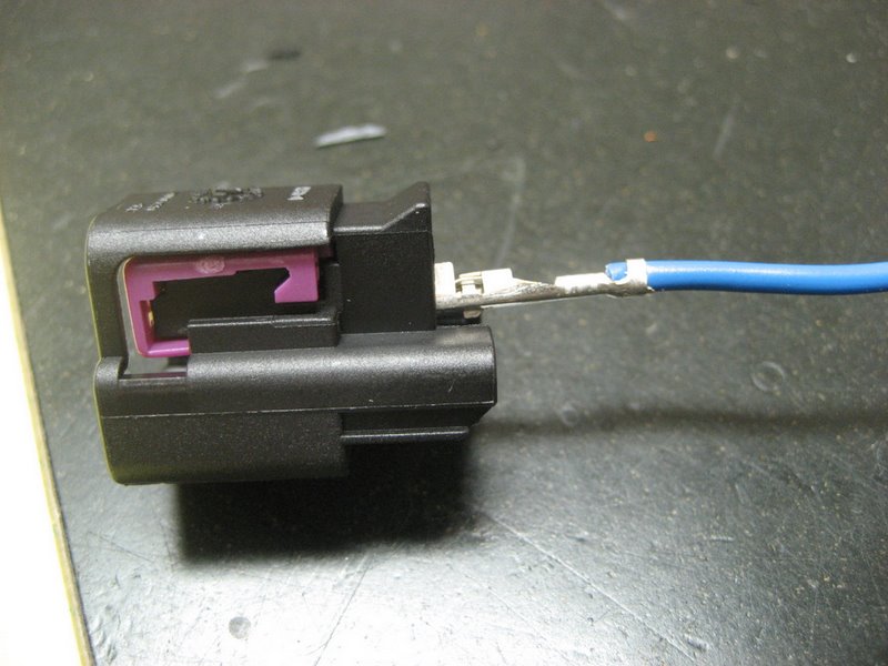
Before locking the Side Lock Cover:
After locking the Side Lock Cover:
Here is the male terminal being inserted into the male connector:
It too has a Side Lock Cover:
Before locking the Side Lock Cover:
After locking the Side Lock Cover:
Here they are connected together:
NOW,
for your PAL installation, push a female connector onto the Pin K terminal and lock the Side Lock Cover.
Cut off the splice connector on the XM wire from the PAL harness and crimp a male terminal to the XM wire:
Push the male terminal into the male connector and lock the Side Lock Cover.
Note: Remember there are TWO positions into which you can insert the terminal.
Be SURE you inserted the terminal into the hole that mates with the female connector
Connect the connectors together at the Splice Pack:
Strap the XM wire to the body harness using a cable tie:
Use another cable tie or two to strap the XM wire to the harness under the dash.
Reinstall the underdash panel, the knee bolster, and the instrument cluster bezel.
Enjoy your PAL even more!
Avoid the Splice Pack area and connect the XM wire directly to the XM receiver connector
Since the Splice Pack area is so hard to get to, this alternative will allow you to connect the XM wire from the PAL wiring harness directly to the XM receiver at its connector. By using this method, you will avoid having to pull the instrument cluster bezel, the knee bolster, the underdash panel. And you can do your work looking down instead of trying to cram your head and two arms in a tiny space below the dash.
This alternative should be particularly attractive to convertible owners, since the XM receiver is located behind the waterfall, not too far from the center console. For coupe and Z06 owners, you will have to route a new wire from the center console area back towards the rear of the car, behind the driver's seat, and then back to the XM receiver above the left rear wheel well.
Here is the Component Location diagram from the Service Manual:
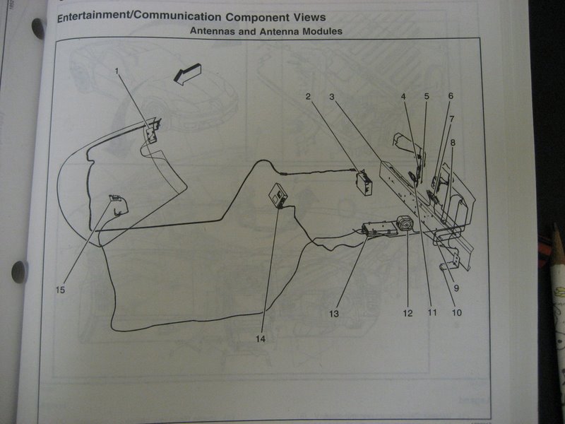
(15) is near the Navigation Unit. A body harness wire runs towards the left of the car, under the driver's door, then up and either rear toward the XM receiver (13) in the Coupe/Z06 or (14) in the Convertible. (The Splice Pack is near the lower left corner of the drawing.) Instead of following this route, your XM wire from the PAL wiring harness will run from the Navigation Unit along the hump under the center console and either up to the XM receiver (14) in the Convertible, or up and over then back to the XM receiver (13) in the Coupe/Z06.
The XM wire from the PAL wiring harness is not long enough to reach the XM receiver location in any Vette. You will need to add about 2' of wire to reach the Convertible XM location or about 6-7' of wire to reach the Coupe/Z06 XM location.
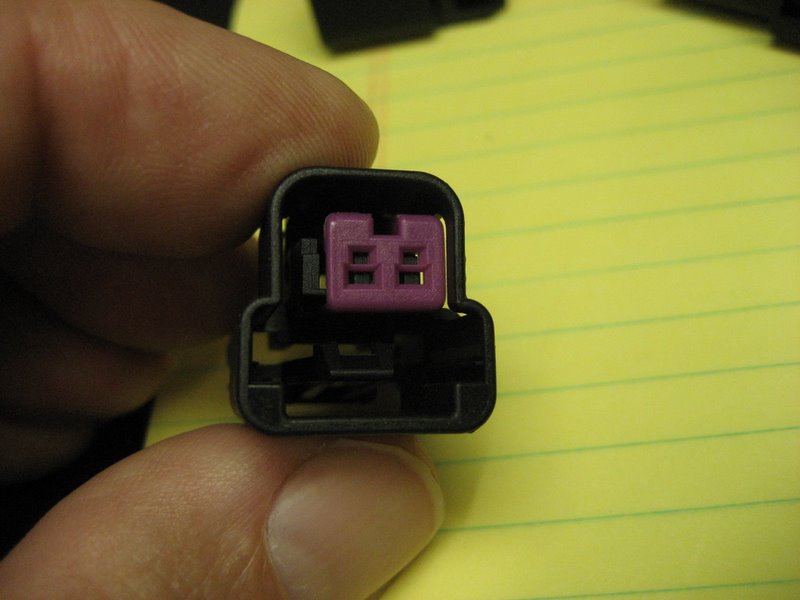
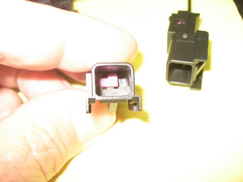
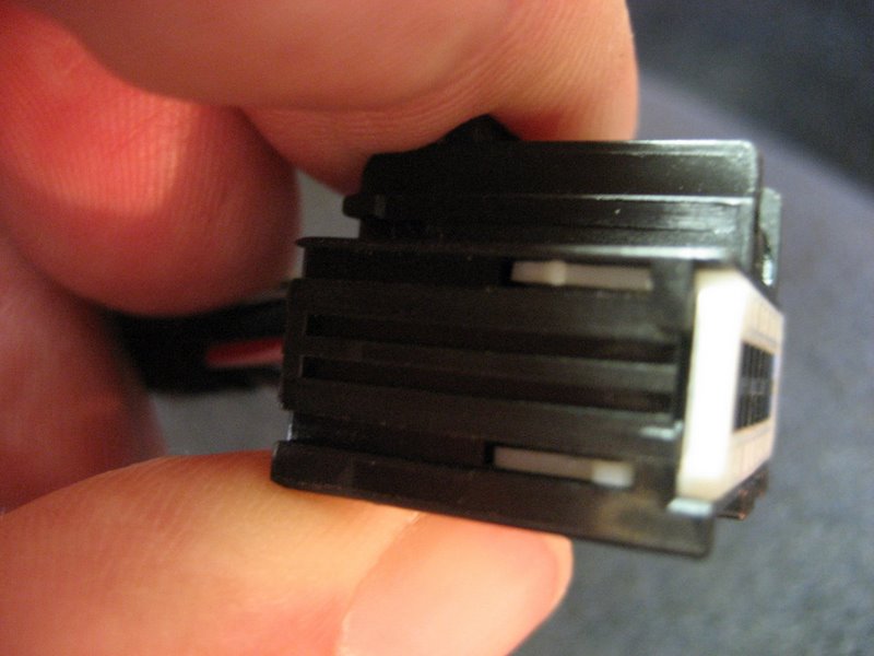
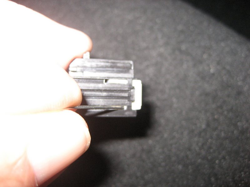
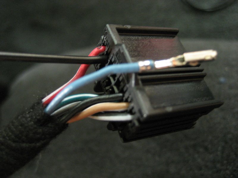
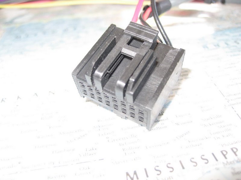
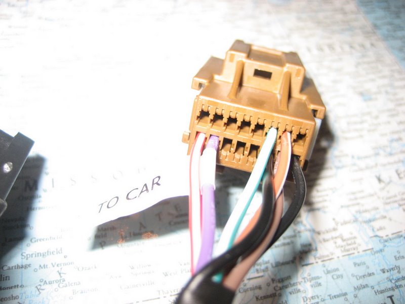
Next, you need to connect this extended wire to the XM receiver connector. This connector is made by Yazaki, part number 7283-9076-30 in 2007 and later Vettes. In earlier Vettes, I'm not sure, because the Service Manual indicates the connector is a Delphi Micro64 connector, part number 15394150. Both are 16 pin female connectors and look somewhat similar. Here is a photo of the Yazaki connector:
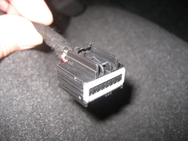
The Delphi connector (if you have it) is identical to the 16 pin PAL module connector on PAL wiring harness. The Yazaki connector is easy to tell apart from the Delphi connector because of the distinctive white TPA (Terminal Protection Assurance) on the front of the connector.
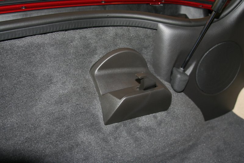
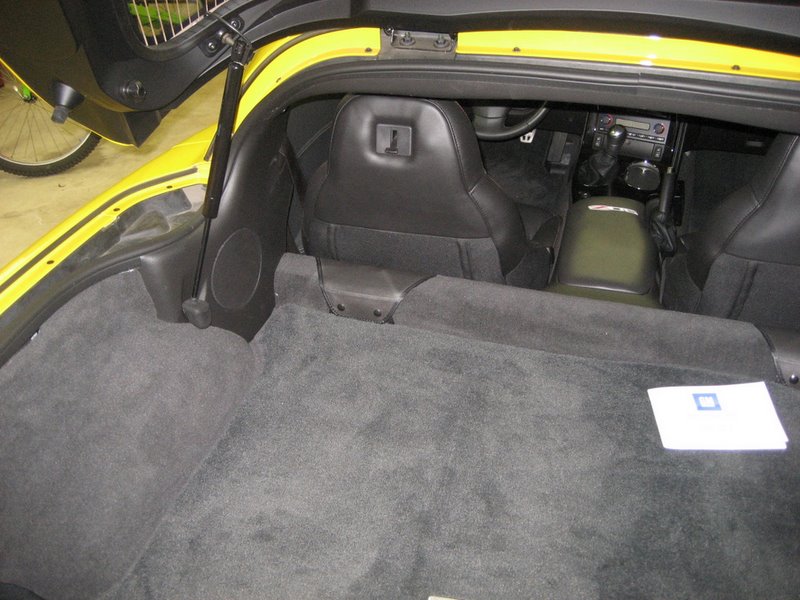
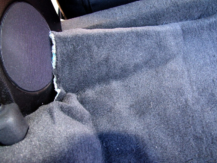
On the Coupe/Z06, here is the XM receiver location (Convertible owners see below):
Pull back the carpet and you'll see the
receiver: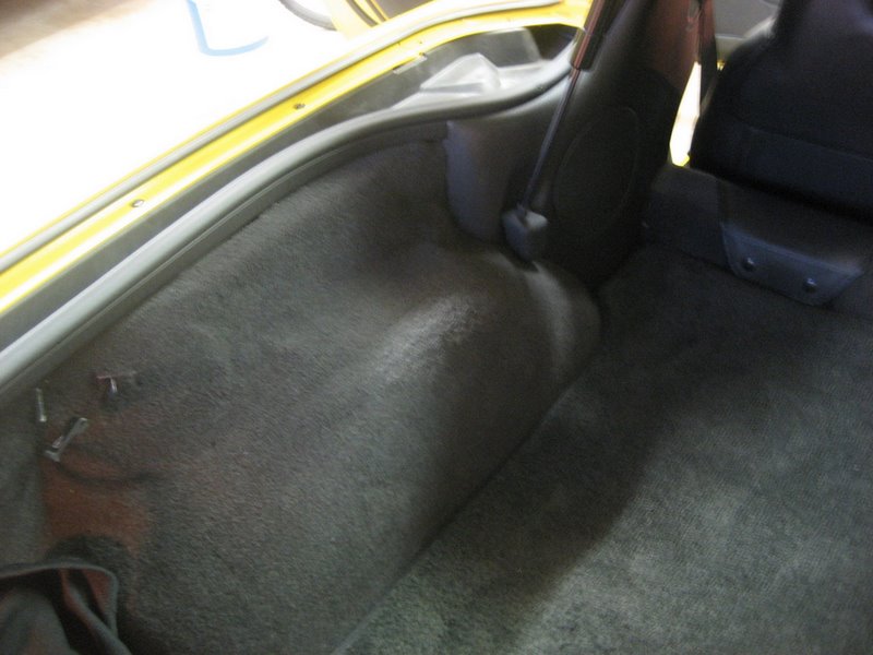
On the coupe, you may have the extra top storage brackets. You may have to remove the left one.
Here are three photos from forum member John Beidl showing the coupe roof storage bracket:
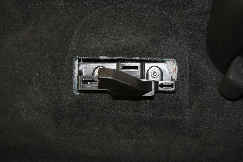
Here are the two plastic clips that hold the receiver in place:
For Convertible owners, you will need to remove the waterfall:
The waterfall is held in by two T15 Torx screws at the top and three plastic pins:
Two of the plastic pins are behind the dividing wall that is in front of the storage area:

If you put your top half way down and look behind the waterfall, you'll see both of them.
The center part of the pin must be pulled out with a small screwdriver to release it:
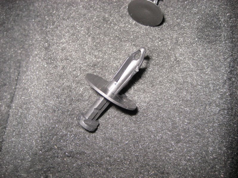
Once the center is pulled out, the main part is able to squeeze together and you can pull the entire pin out.
The third pin is on the passenger side of the waterfall:
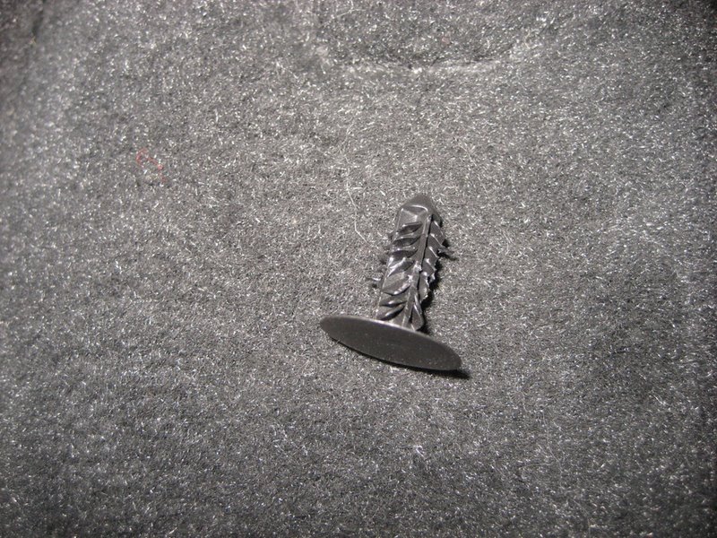
This one is a bit hard to grab because the head lays flat against the painted waterfall, so don't damage the paint.
Get something flat behind the head (fingernails?) and pull to get it partially out. Then use some bent needlenose pliers to pull out the entire pin. Just pull hard and it will come out.
Once the three plastic pins are out and the two Torx screws removed, the waterfall lifts out.
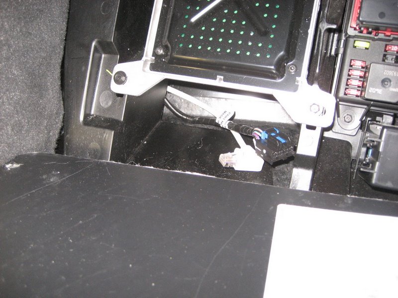
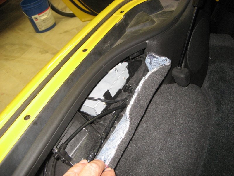
Here is where you'll find the XM receiver (Yazaki connector is pulled out in this photo):
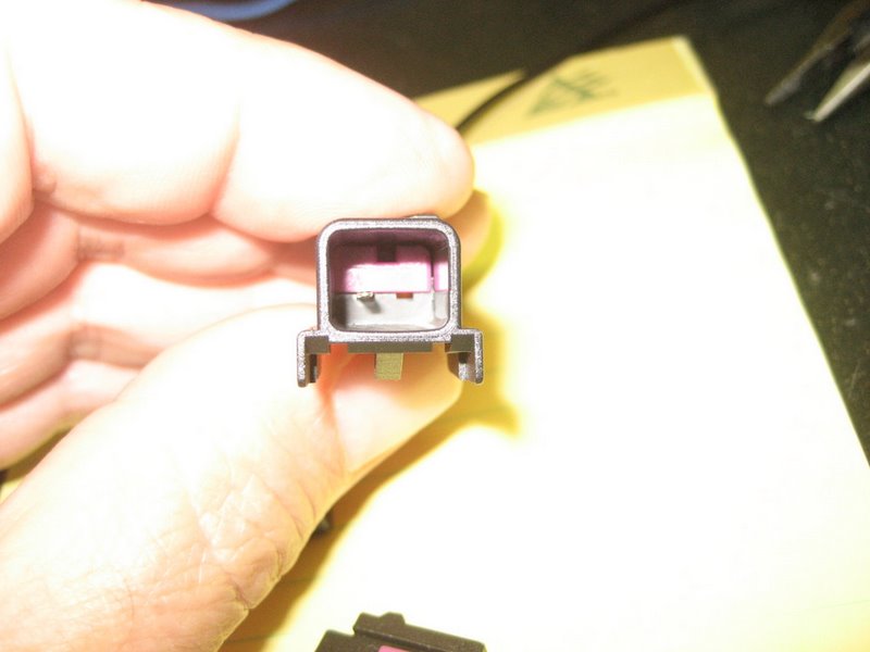
Here's a closeup of the Yazaki connector:
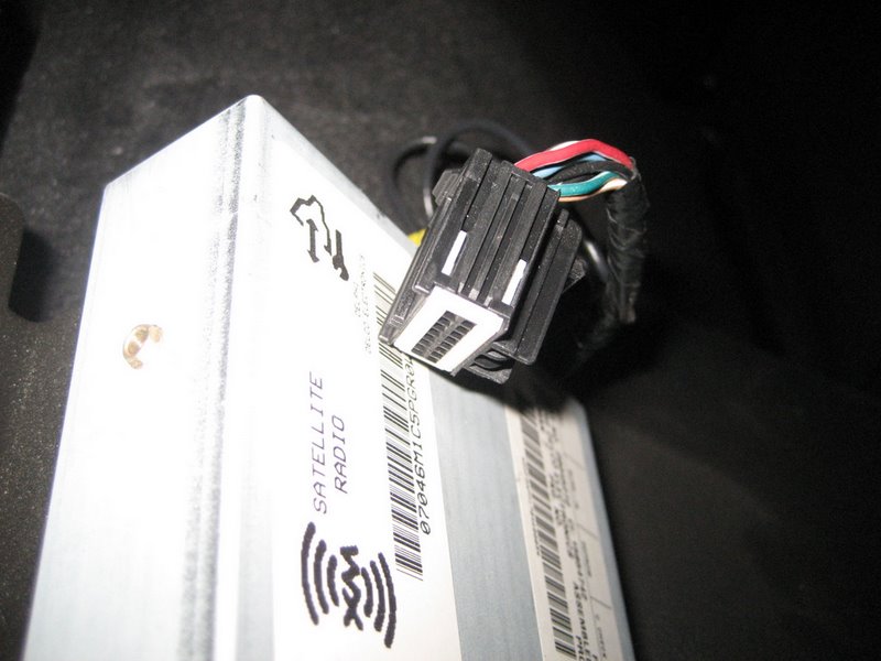
It's the same connector as in the coupes and Z06s.
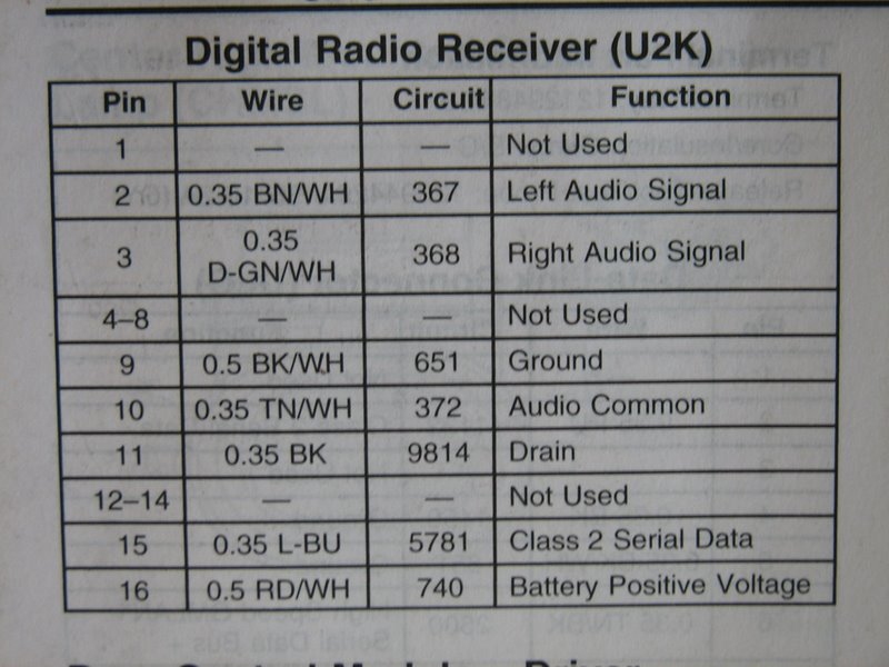
Here is the Pinout chart for the XM receiver connector. We are interested in Pin 15, the light blue wire for Circuit 5781, Class 2 Serial Data.
This is the same wire that connects to Pin K of the Splice Pack SP205 up under the dash.
What we want to do is disconnect the XM receiver from main serial data bus (the light blue wire) and instead connect it to the "XM wire" directly from the PAL module:
Pull out the XM receiver so you can then remove the 16 pin Yazaki connector.
The light blue wire at Pin 15 is next to the red/white wire at Pin 16:
Pull back some of the outer cable sheath so you can expose a couple of inches of the light blue wire.
Cut the light blue wire about two inches from the connector.
It is very important that the copper conductor of the cut wire in the body harness not touch anything! So either pull some of the insulation over the end of the wire or tape off the wire or use heat shrink tubing over the end of it. If this exposed end of the wire were to touch something electrical or get grounded, your car may not even start. This is very easy to protect, but be sure you do it.
OK, the light blue wire in the body harness is taped off, so now you need the 2" end of the light blue wire connected to Pin 15 of the connector. Strip off some insulation and either solder or crimp on a splice connector so you can now connect the extended XM wire from the PAL wiring harness to this 2" light blue wire.
Route this XM wire from the XM receiver, behind the speaker on the left, then under the carpet behind the driver's seat, then along the center console. I'm hoping a coupe/Z06 owner who uses this alternative will forward some photos to me via email so I can post them on this web page. There is no location that you MUST follow - just get the wire from the center console area and the PAL wiring harness to the XM receiver.
For convertible owners, it will be a much shorter route from the PAL wiring harness to the XM receiver.
Click on this link for John Beidl's writeup and photos for routing the new XM wire:
http://www.kawal.net/PAL%20wire%20routing.htm
For convertible owners, the above web page should also help, because not only is the route much shorter, but if you remove the console extension (only three bolts and the connector) you can easily route the new XM wire.
Once it is connected and the remaining installation of the PAL module and the Ipod cable is finished, you can turn on the PAL and enjoy it.
Avoid the Splice Pack area and connect the XM wire directly to the XM receiver connector, but do not cut the light blue wire
The wiring of this alternative is exactly the same as Alternative 3, but you don't have to cut light blue wire if you have the proper terminal to modify the connector wiring.
The Yazaki connector, part number 7283-9076-30 is a 064 series connector with spaces for 16 female terminals. The part number for the terminals are provided incorrectly in all of the Service Manuals. The correct Yazaki part number is 7116-4619-08 or 7116-4619-02 for 18 gauge wire or 7116-4618-08 or 7116-4618-02 for 20-22 gauge wire.
To avoid cutting the original light blue wire at Pin 15, a neater way to make this connection is to pull the original terminal on the light blue wire out of the connector and tape it off SECURELY so it can't touch anything. Then insert a new terminal and wire that connects to the XM wire of the PAL wiring harness into the Yazaki connector at Pin 15. This is quite simple to do if you have the correct terminal. Here's how:
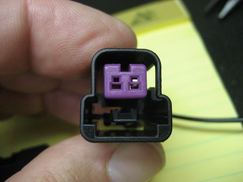
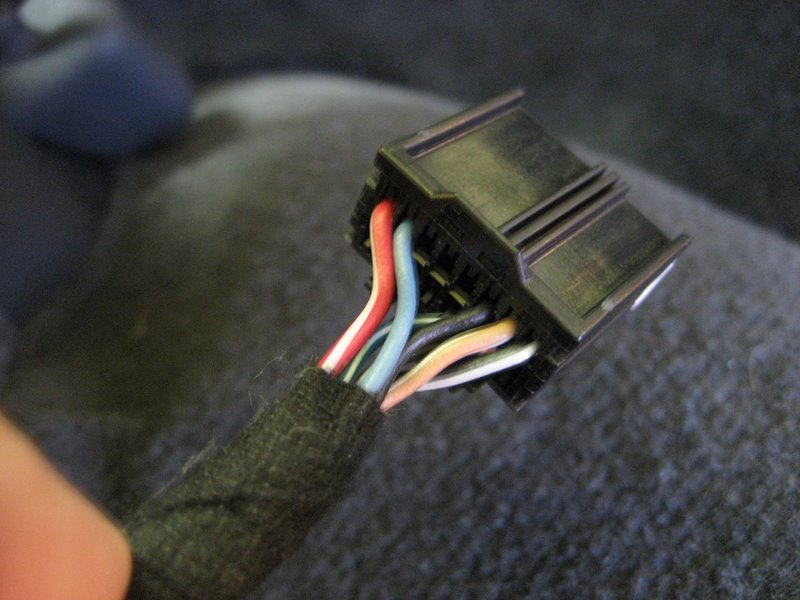
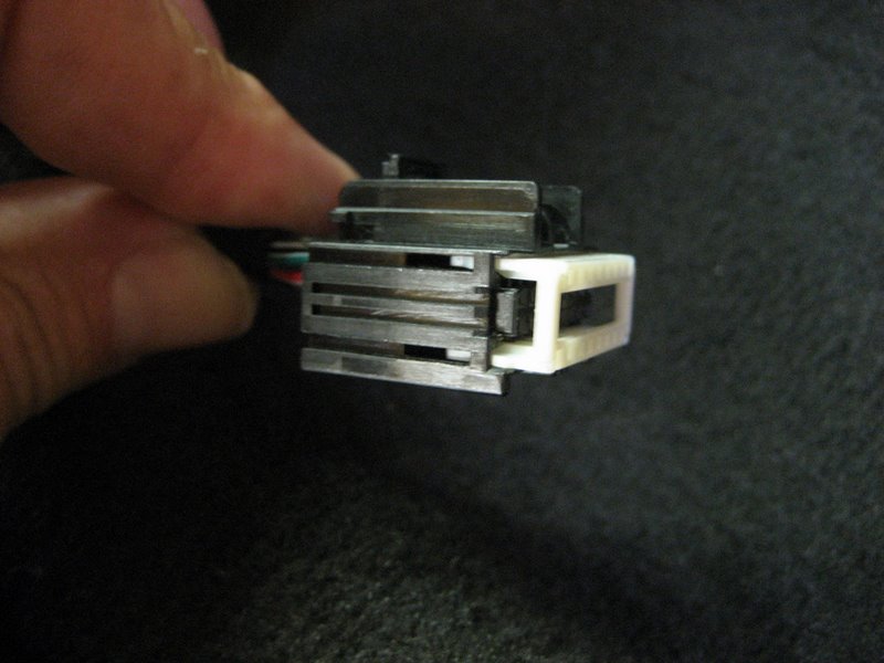
First, examine the Yazaki connector:
and the wiring, as before:
A close up photo reveals how the TPA is inserted:
The TPA in this position prevents any terminal from being removed. Take a look at how the connector is constructed.
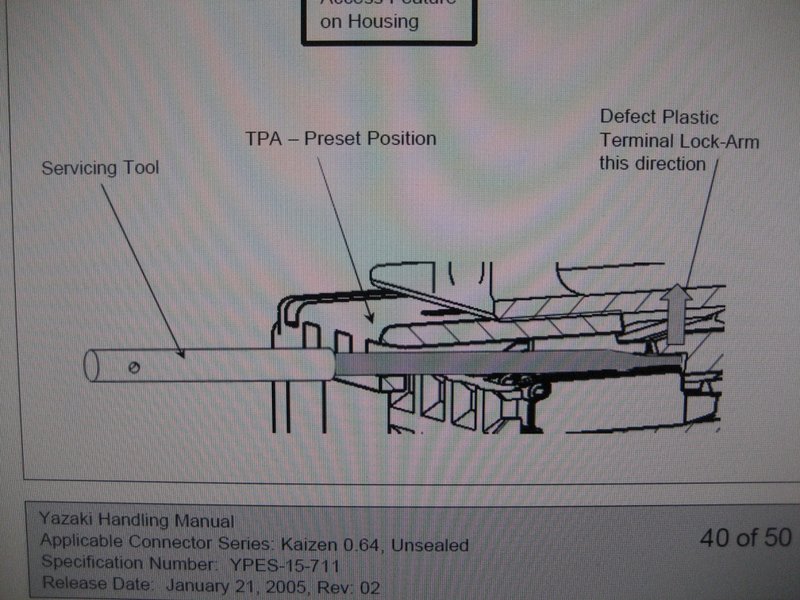
First, here is the terminal. See the "Lock-Up Feature"? This is what locks the terminal in the connector.
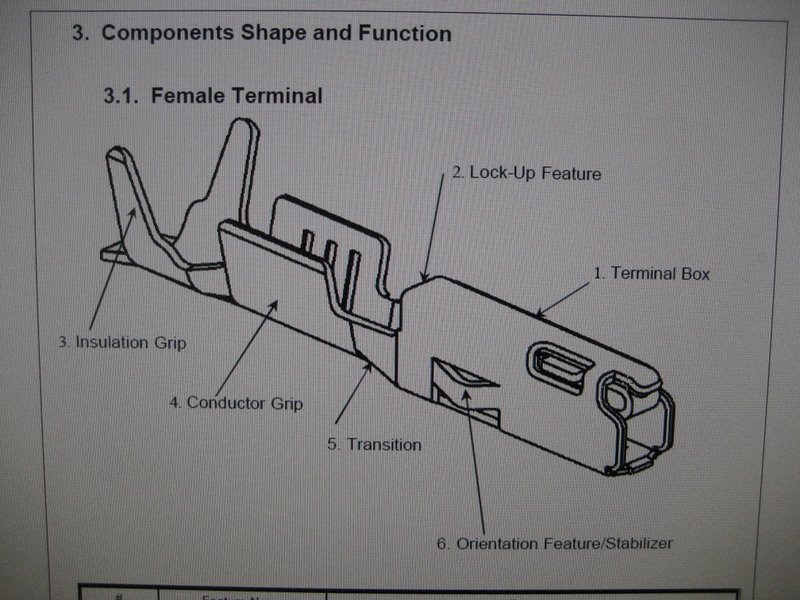
The Plastic Terminal Lock-Arm (3) catches the terminal Lock-Up feature:
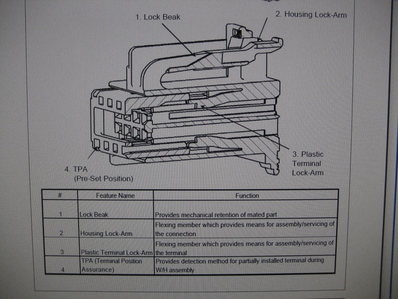
When the TPA is pushed all the way in, the Lock-Arm cannot be pushed up out of the way. So the terminal is locked in.
So, to remove the terminal, you pull out the TPA to the "Pre-Set Position" by pushing on both sides as shown:
Here is the TPA in the Pre-Set Position:
To remove a terminal, you need a tool to push up on the Plastic Lock Arm. Notice the angle of the tool end:
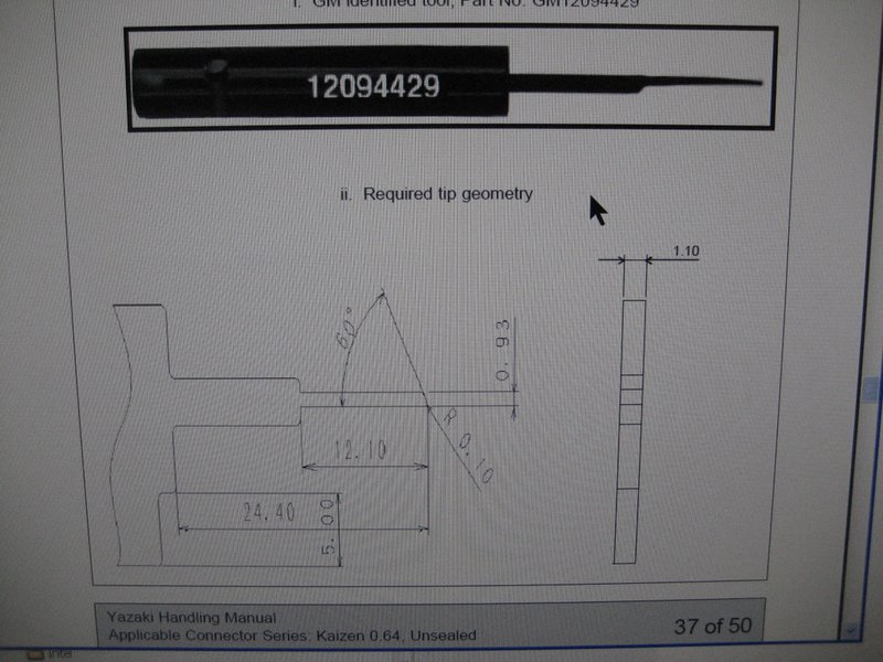
But a standard paper clip will work just fine as a tool.
It helps to grind the end of the paper clip at an angle as shown:
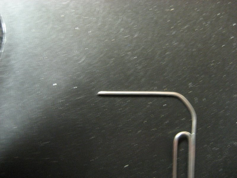
See how the tool is used to pry up the Lock-Arm:
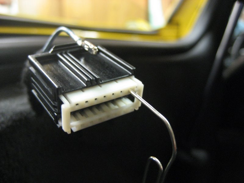
Stick the paper clip into the servicing hole at Pin 15 and the Plastic Lock-Arm will deflect.
Jiggle the terminal at Pin 15 and it will come out.
If you have a bit of trouble, try removing the TPA altogether. Once the Lock-Arm is deflected the terminal will come out easily:
Another view:
This terminal should be folded back and taped VERY WELL so it can never touch anything!!!
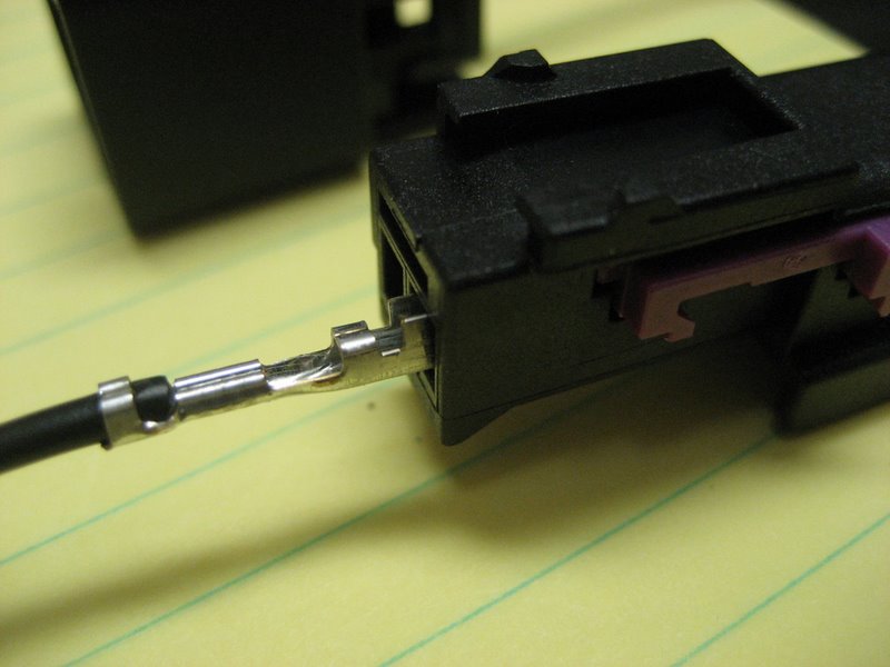
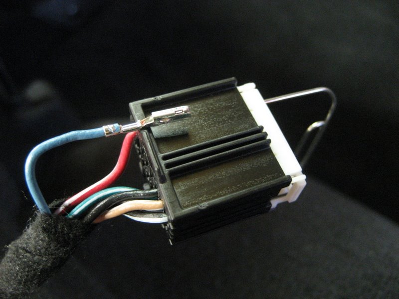
A new wire and terminal is simply inserted back into the connector at Pin 15. It will click into place, then push the TPA back into its locked position:
Here is a photo of the new wire and terminal being inserted:
Don't forget to fold back and tape off the light blue wire securely. This wire is still connected at the Splice Pack to the main serial data bus, and you don't want it touching anything.
The new XM wire is fully inserted:
Be SURE to reinstall the TPA!
So, to complete this Alternative 4 you will need a wire crimped onto a Yazaki terminal.
If you email me at ray@kawal.net and provide your address and five bucks, I'll send you a wire with a Yazaki terminal crimped on. You will then install the terminal per the above instructions and run the wire from the XM receiver back to the XM wire on the PAL wiring harness near the center console area. Cut the wire to a convenient length and crimp in onto the XM wire using the splice connector on the harness or solder it on if you prefer.
You can use Paypal and my email address or send me a check, cash, or money order - whatever is easiest. I'm just trying to recover my out of pocket costs, so I'll trust you to send the bucks after I get the wire and terminal kit in the mail to you. I know you are anxious to get it done, so I won't wait for your check to clear and all that.
Also, please let me know whether you have a Vert or a couple/Z06. I'll have the Vert wire about 3' long and the coupe/Z06 wire about 8' long. If I make them all 8' long I may run out of wire and both of those lengths should be plenty long enough - please let me know how much you use so I can cut future lengths appropriately.
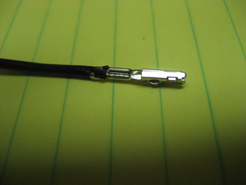
Here is a photo of the new Yazaki terminal crimped onto a new 20 gauge wire:
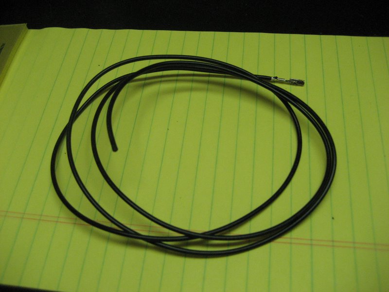
And the completed wire kit (this one is for a convertible, 3' long):
Update as of 8/10/09:
A few owners have had a bit of trouble fitting this wire and crimped terminals into the Yazaki connector. The original wire in the factory harness is 22 gauge wire rather than the larger and more robust 20 gauge wire, which I used successfully in my own car. If it is too tight for you who have already received a kit from me, first try to squeeze the terminal a bit with some needlenose pliers. It should then fit snugly into the connector.
If you damage the terminal or just can't get it to fit, email me and I will send you a new kit with 22 gauge wire. All future kits I send out will use the smaller wire.
Click on this link for John Beidl's writeup and photos for routing the new XM wire:
http://www.kawal.net/PAL%20wire%20routing.htm
For convertible owners, the above web page should also help, because not only is the route much shorter, but if you remove the console extension (only three bolts and the connector) you can easily route the new XM wire.
An Ultra Simple PAL Installation using a custom wire harness
How would you like to have your PAL working in 5-10 minutes instead of 5 hours?
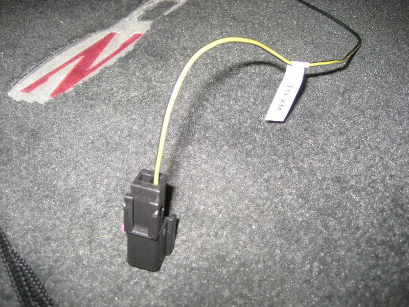
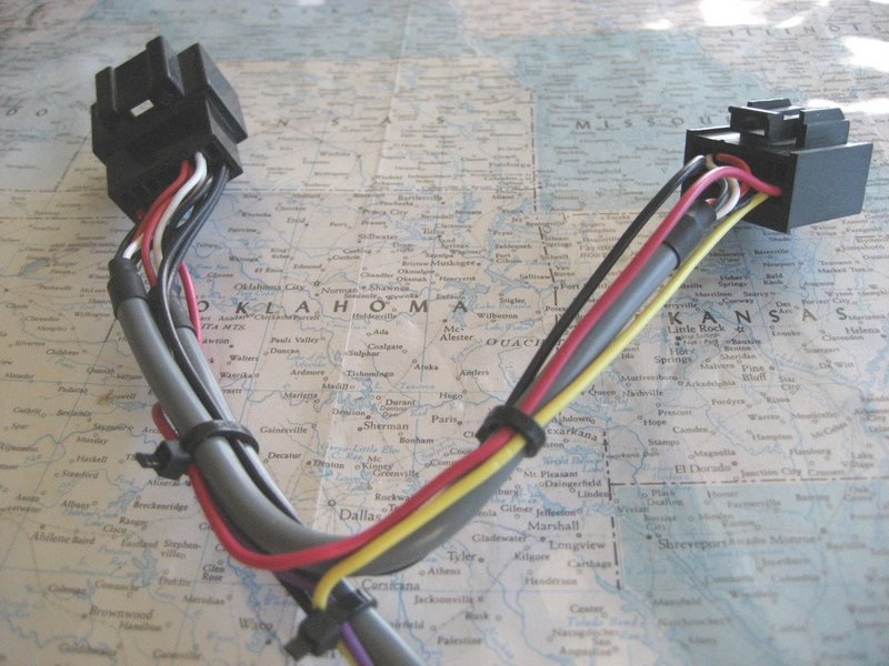
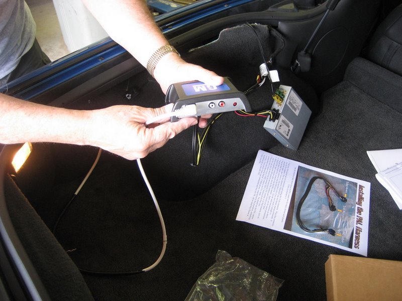
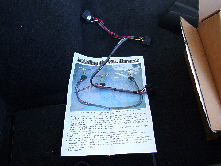
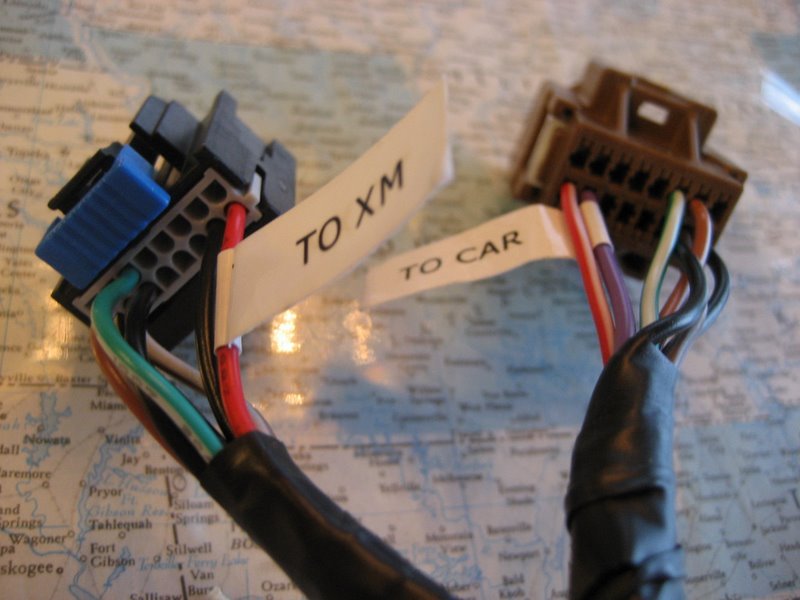
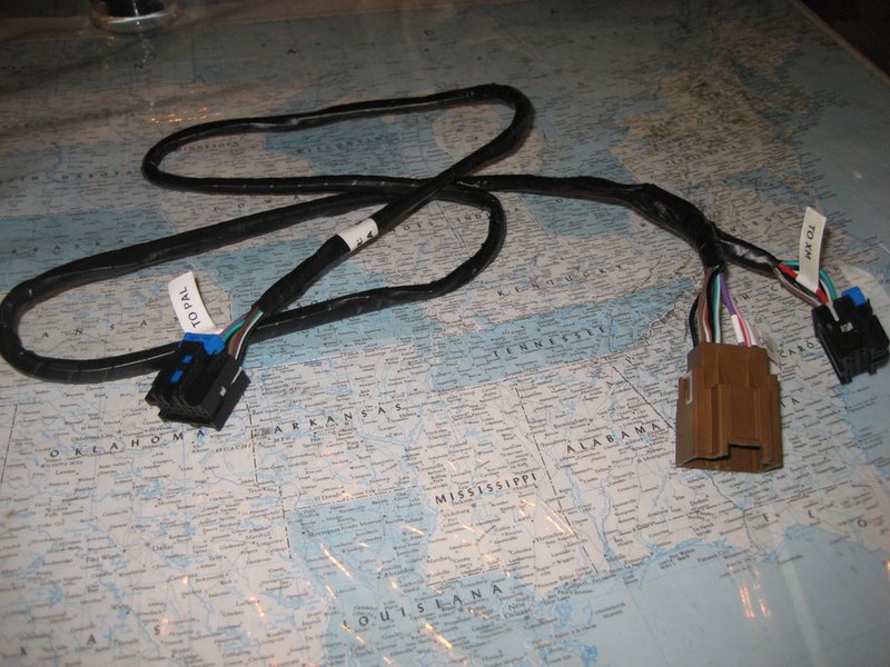
This new harness will do the trick:
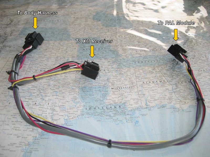
Unlike the installation with the standard GM PAL harness, you won't have to remove your center console, Nav unit, glove box, or take your instrument cluster apart just to get to the "infamous" splice pack. Instead, forget about all of that work and get to your easily accessible XM receiver.
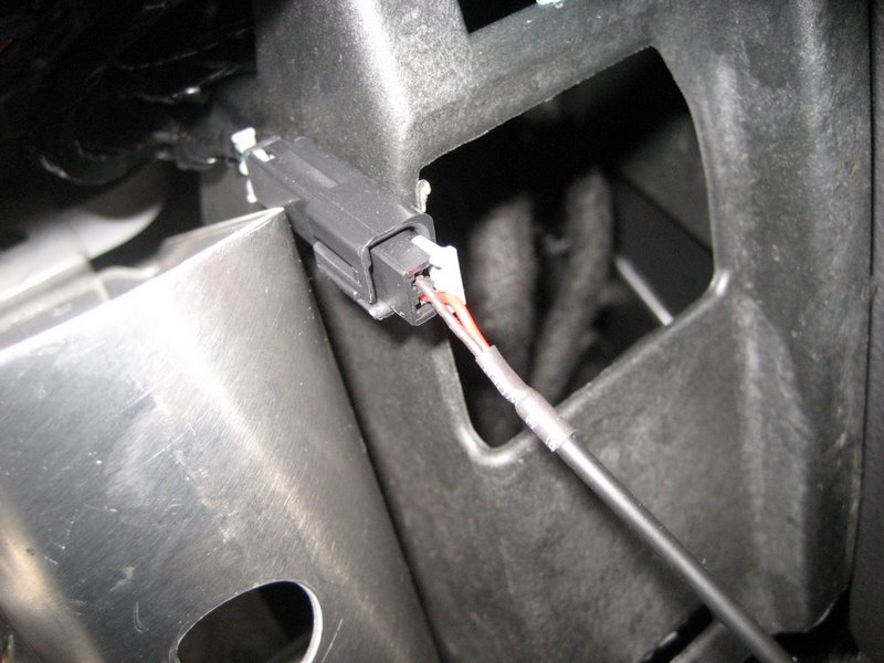
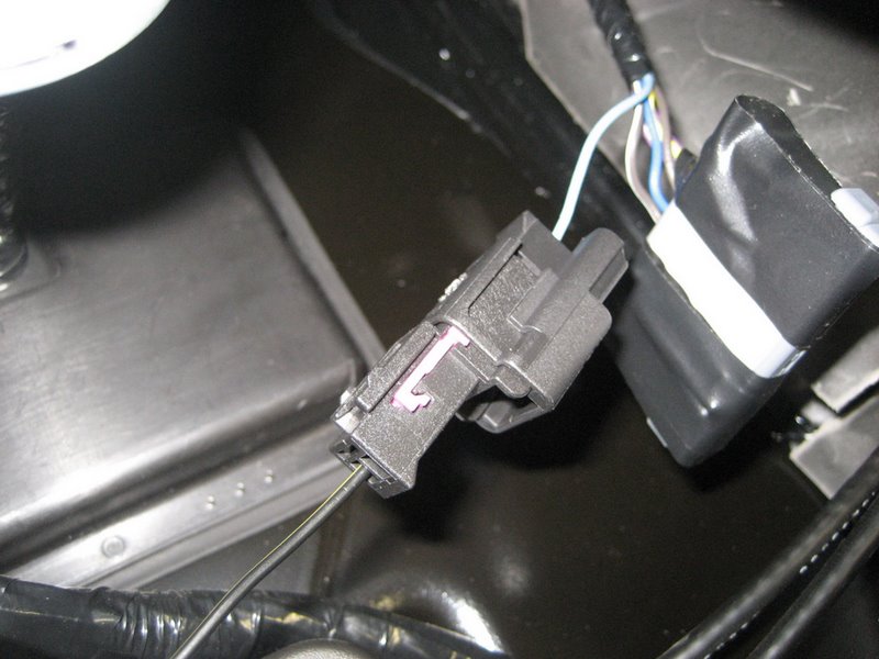
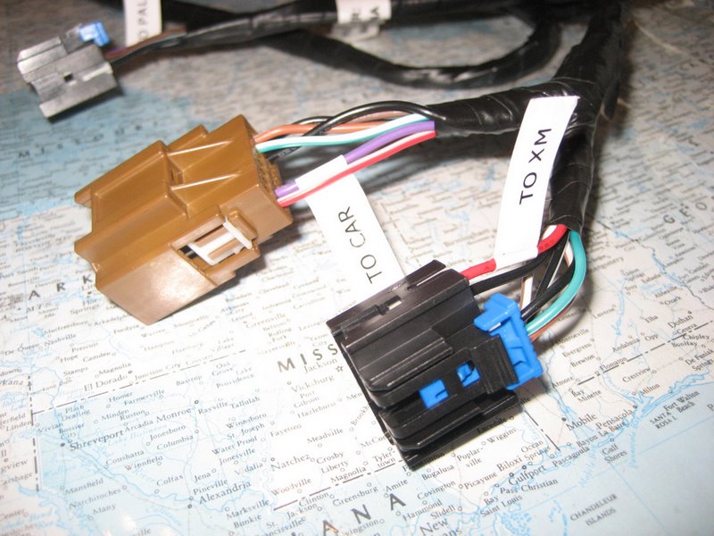
These three connectors will simply plug into your XM receiver and your PAL module to connect them together. Here's how it works.
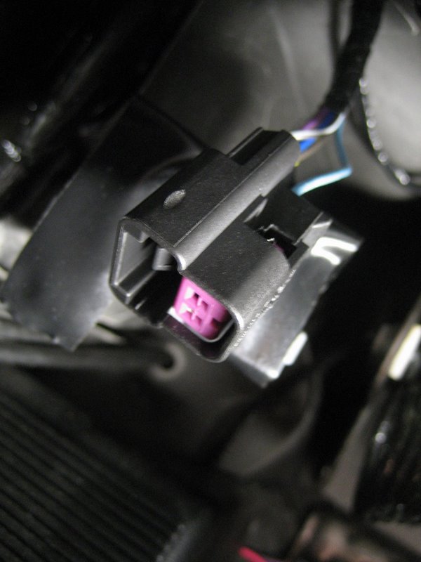
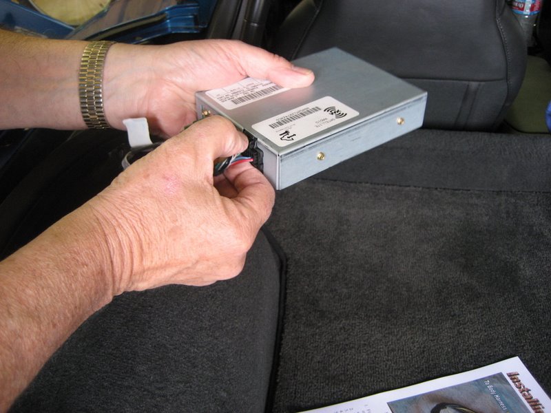
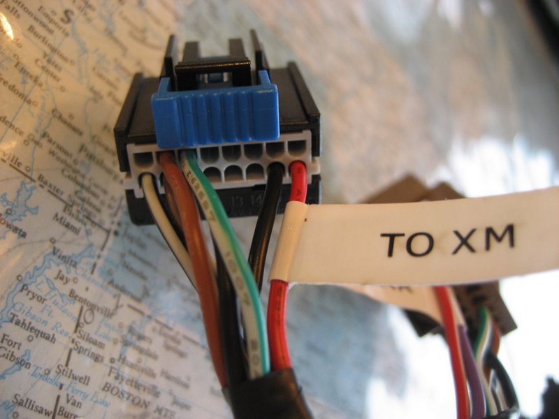
First unplug your XM receiver (more details later):
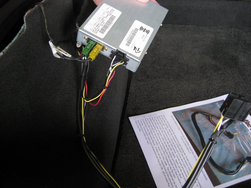
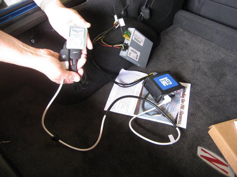
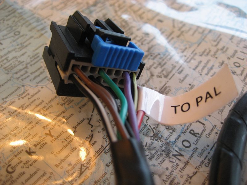
Next, plug that connector into the new body harness connector on the custom wire harness:
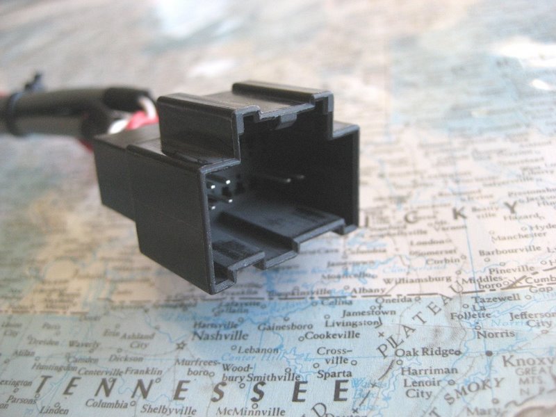
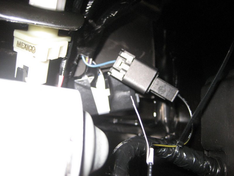
Here's another photo of the body harness connector from the back:
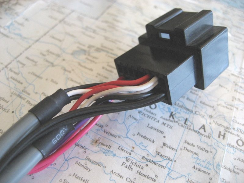
Next, connect the new XM connector to the XM receiver. Here's a photo:
And another photo from the back:
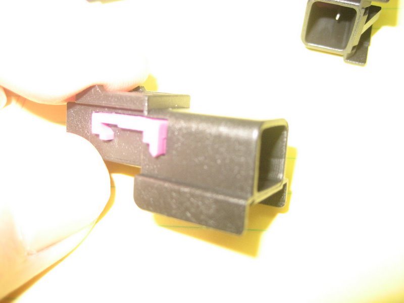
Here's a closeup of the two male and female connectors:
These two connect the XM receiver while rerouting the Class 2 serial data information through the PAL module.
It is important to note that the connector to the XM receiver (on the right, above) is on the SHORT cable.
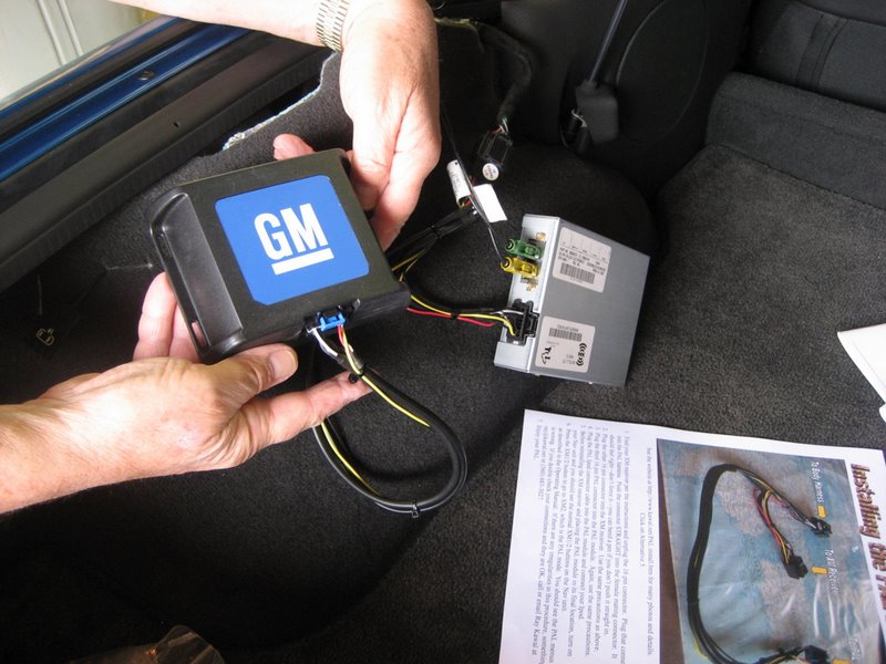
Next, plug the third connector on the LONG cable into the PAL module:
This PAL module connector is exactly like the XM receiver connector, but they can NOT be interchanged.
The wiring on each connector is specific to the module it connects.
That's all there is to it!
Once you plug in the Ipod cable into the PAL module and connect your Ipod, your PAL will operate exactly as explained in the Operating Manual.
Click here for Ordering Information
Now for some more details:
(Some of this is duplicated from other installation Alternatives)
1. FOR CONVERTIBLE OWNERS
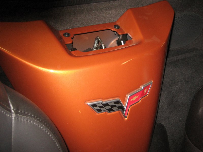
To get to your XM receiver, you need to remove your waterfall between your seats:
The waterfall is held in by two T15 Torx screws at the top and three plastic pins:
Two of the plastic pins are behind the dividing wall that is in front of the storage area:
If you put your top half way down and look behind the waterfall, you'll see both of them.
The center part of the pin must be pulled out with a small screwdriver to release it:
Once the center is pulled out, the main part is able to squeeze together and you can pull the entire pin out.
The third pin is on the passenger side of the waterfall:
This one is a bit hard to grab because the head lays flat against the painted waterfall, so don't damage the paint.
Get something flat behind the head (fingernails?) and pull to get it partially out. Then use some bent needlenose pliers to pull out the entire pin. Just pull hard and it will come out.
Once the three plastic pins are out and the two Torx screws removed, the waterfall lifts out.
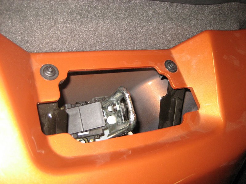
Here is where you'll find the XM receiver (Yazaki connector is pulled out in this photo):
Here's a closeup of the Yazaki connector:
It's the same connector as in the coupes and Z06s.
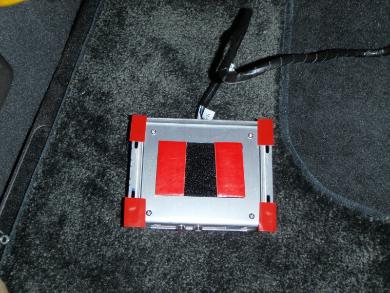
Mount your PAL module using the velcro tape directly to your XM receiver and use the new harness to connect them together.
Plug in the 8' PAL Ipod cable into the PAL module and run the cable forward to your choice of locations for your Ipod. The new iPod cables will charge all of the latest iPods and iPhones.
Update 9/8/09:
Richard Hughes had an installation issue with his convertible installation. Here is his initial mounting of the PAL module:
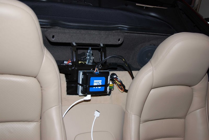
And a closer view:
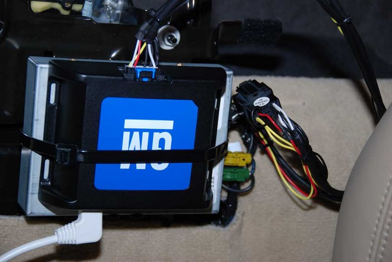
When he reinstalled his waterfall, he found he had some interference:
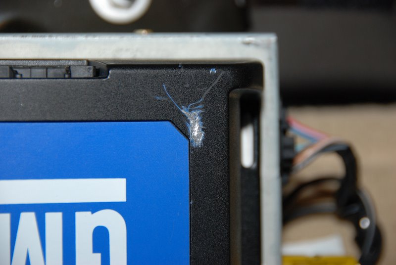
He found his Corvette emblem mounting pins protruded through the waterfall:
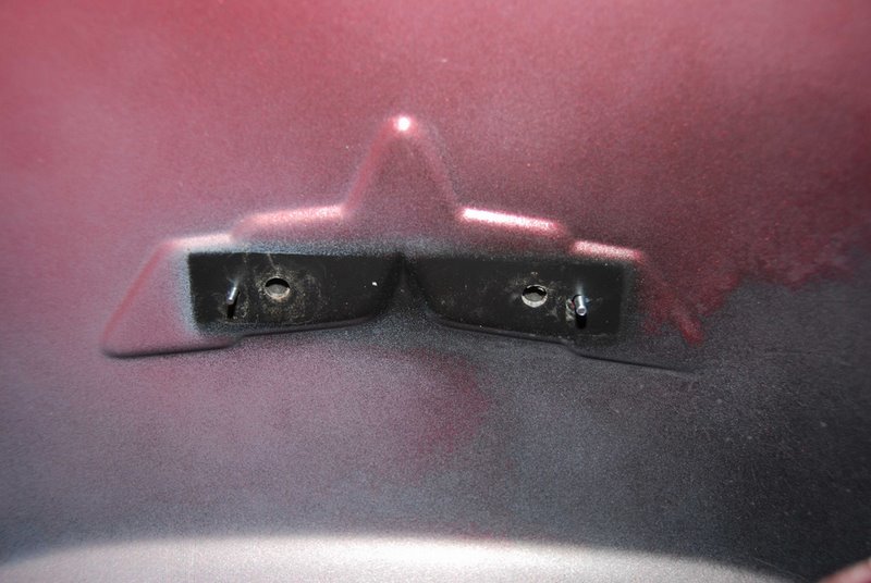
A closeup:
This was enough to cause interference with the PAL module. So he moved the module down:
There could be other positions in which the PAL module won't interfere with the waterfall, but you should check your fit before you reinstall it.
2. FOR COUPE/Z06 OWNERS
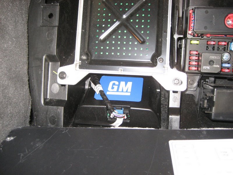
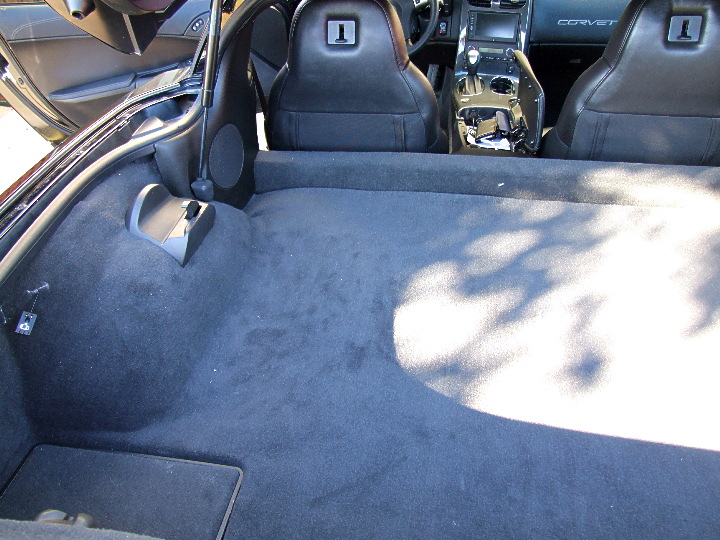
Your XM receiver is located above the left rear wheel well:
On the coupe, you may have the extra top storage brackets. You may have to remove the left one.
Here are three photos from forum member John Beidl showing the coupe roof storage bracket:
Lift up (pull hard if necessary):
Here are the clips that show how the bracket is held in place:
Here are the two plastic clips that hold the receiver in place:
If you can reach the connector and pull it out, you don't have to remove the XM receiver. Otherwise, you can unclip the receiver and lift it out - there are three mounting studs (one shown) that are not used in the coupe/Z06s that get in the way a bit, but the receiver will come out. After it's out, I'd suggest you also remove the plastic tray (see the clip into the fiberglass?) just so you can see how it and the receiver mount. The tray is very easy to get back in, and understanding how it is mounted will help you reinstall the XM receiver.
As previously described, unplug the connector and reconnect the XM receiver using the new harness. Move the PAL end of the harness towards the rear of the car so the PAL module can sit behind the XM receiver above the wheel well. Connect the PAL module with the third harness connector and connect the PAL Ipod cable to the PAL module.
The new 8' PAL iPod cables are long enough to reach anywhere in the center console area. They will also charge all of the latest iPods and iPhones.
Click here for lots of Frequently Asked Questions about the PAL
Now, for this Alternative installation, you need the custom installation harness.
I have these new harnesses in stock, and I offer these new installation harnesses for $35 plus your original PAL harness in return plus $5 Priority Mail shipping to any U.S. address. If you wish to keep your original PAL harness for any reason, please add $15 to the total cost. (I can ship to other countries as well.)
I can ship immediately via USPS Priority Mail. So if any owners would like to install their PAL using this alternative, you can either use Paypal to my email address or send me a check or money order. Email me with your complete shipping address, and I will send out the harness as soon as I receive your payment.
![]() Click
here for a new ordering site that will allow payments by credit card as well.
Click
here for a new ordering site that will allow payments by credit card as well.
As another alternative, I also now offer a "Premium" harness for $65 plus $5 Priority Mail shipping plus your original PAL harness in return. When you receive the new Premium harness, and get your PAL operating, I'll need you to send the original back to me. Anyone interested in this "Premium" harness should click here for Alternative 5a.
If you have any questions, you can email me at ray@kawal.net
The First Actual PAL Installation (9/1/09):
Today, forum member Steve Yabroff (Lead Foot 66) drove his '08 Z06 over to Sequim to install his new PAL package using the new PAL harness. It took about 5 minutes to have his PAL working on his Nav Unit. But we spent probably an hour total, by the time the PAL module and the XM receiver were reinstalled and the Ipod cable was routed. The following photos should help others install their PAL in their coupes or Z06s. Convertible owners will have a considerably easier time, because of how their XM receiver is mounted and located close to the center console.
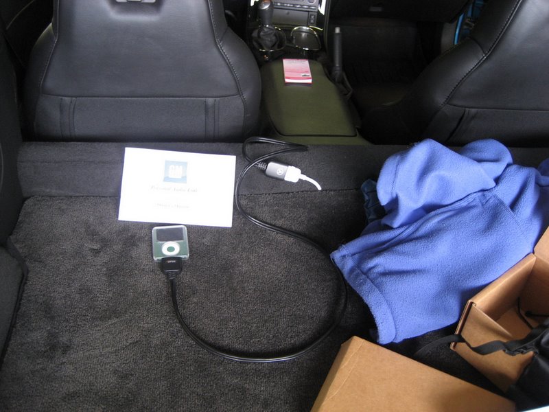
Here we begin the installation:
Above the instruction page is where the XM receiver is located.
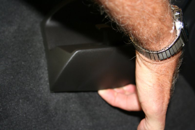
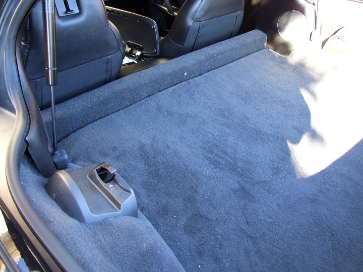
Just grab the carpet and pull it out (note that coupe owners may have to remove the spare top bracket - see previous photos):
Previous photos showed how the XM receiver is held in place in the plastic tray.
See those three mounting studs on top of the receiver? They are for convertible mounting, so all they do in the coupe/Z06 is get in your way. You work the XM receiver out of the tray (maybe cussing a little as those studs catch on the body), but be patient and don't force anything. It took about a minute or two for Steve to get the receiver out and in his hands as shown.
Next, we disconnected the XM receiver:
Next, plug in the new harness:
Then the PAL module:
You will have to later disconnect the PAL to mount it (as shown in following photos), but we are connecting it to make sure everything works. It just takes a few seconds.
Next, connect the PAL Ipod cable :
Steve chose to add a 4' extension and charging adapter. This was before the latest 8' iPod cables became available that will easily reach the center console area. The new cables will also charge all of the latest iPods and iPhones.
Once you connect your Ipod to the new cable, put your Vette in Accessory mode and turn on the Nav unit. You'll see the normal screen with XM1/2 buttons on the left. Push the XM1/2 button to go to XM2 - this is the PAL mode. Here is Steve's Nav screen with the PAL menu:
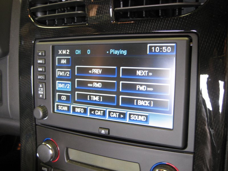
At this point, your PAL is fully operational. The Operating Manual will lead you through how it works.
To get this far, we've spent no more than five minutes.
OK, the PAL works, so we've got to reinstall the XM receiver and hide the PAL module.
Pull out the plastic XM receiver mounting tray and examine it:
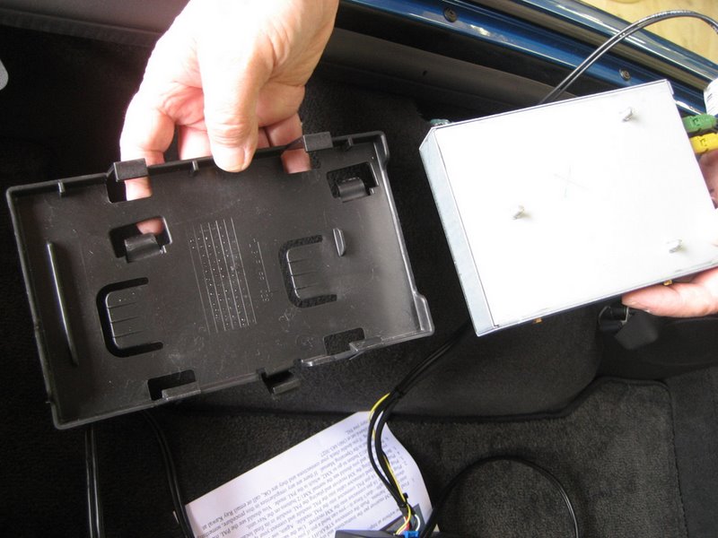
The receiver locks in place between the tabs just above and just below the two U shaped cutouts:
Here's how it's mounted in the tray:
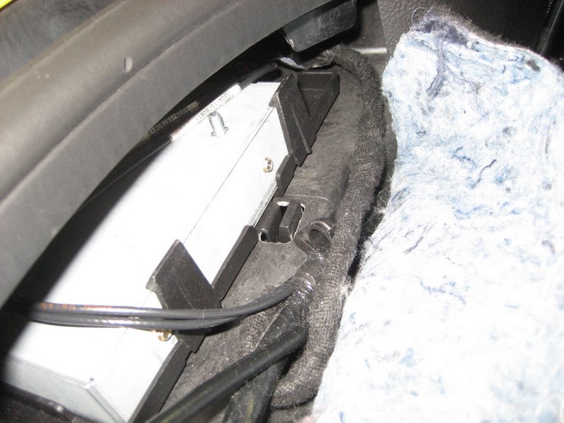
For reinstalling the XM receiver, first disconnect the PAL module (leaving the XM receiver connected) and move all of the cables out of the way. You could probably set the receiver AND tray back in place, but we chose to first reinstall the tray, THEN snake in the cables and XM receiver. BE CAREFUL of those cables and wires - treat them with reasonable care - you don't want to break a wire or pull a terminal out of the connector. Again, those pesky mounting studs might make you swear a little:
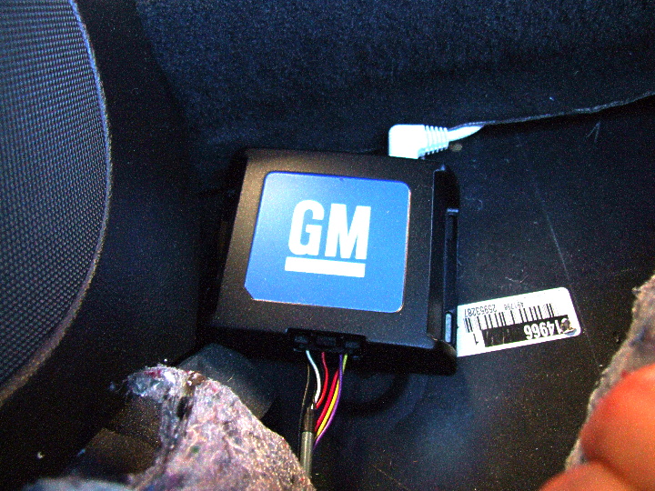
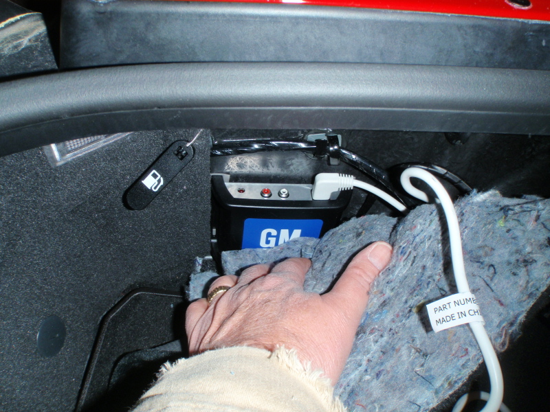
Route the PAL connector behind the structure shown. Pull it gently out and tuck the remaining XM receiver cables in above the receiver:
Again, reconnect the PAL module. There is no solid mounting method for the module, but if you add some padding, it will fit nicely in back of the XM receiver area:
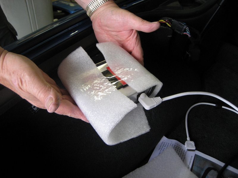
Here it is in place:
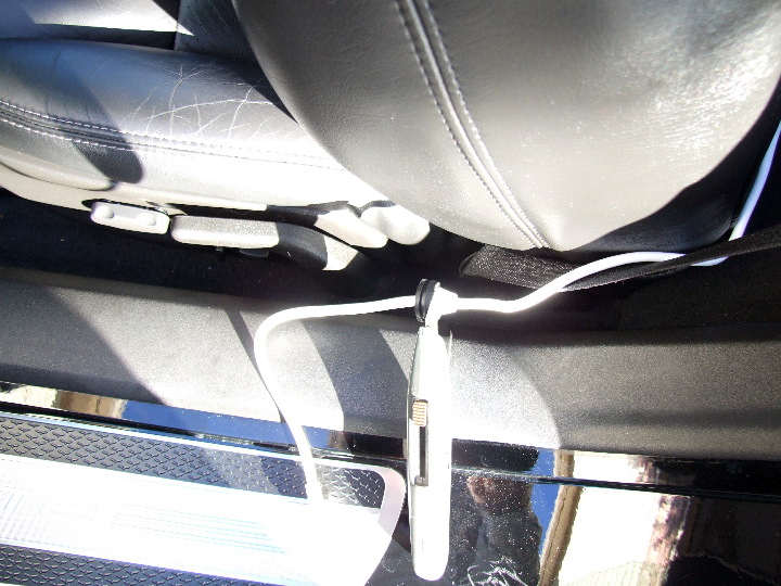
At this point a personal choice must be made - where do you want your Ipod?
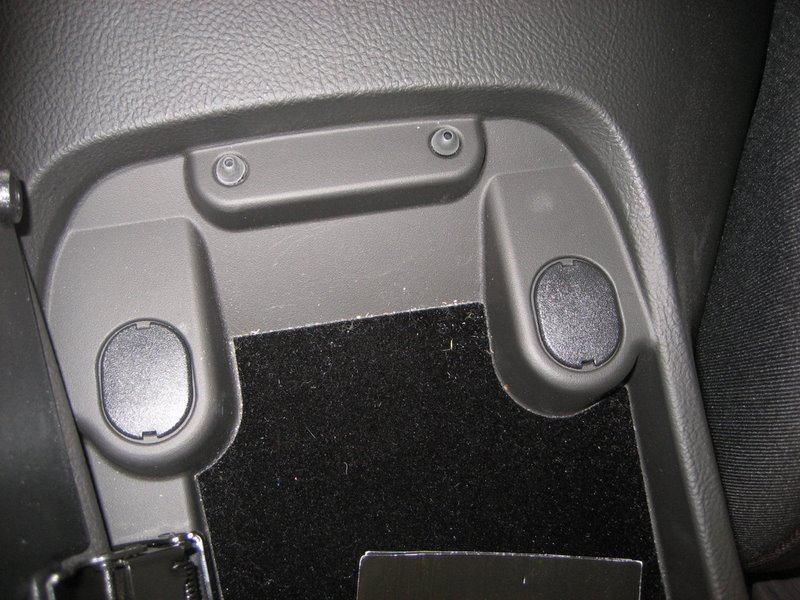
If you want it in the left rear storage compartment, that's easy - just route the Ipod cable under the carpet to back there.
If you want it near the center console like Steve did, route the cable forward, along the existing cables.
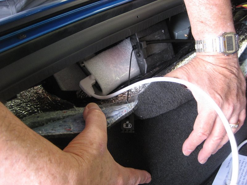
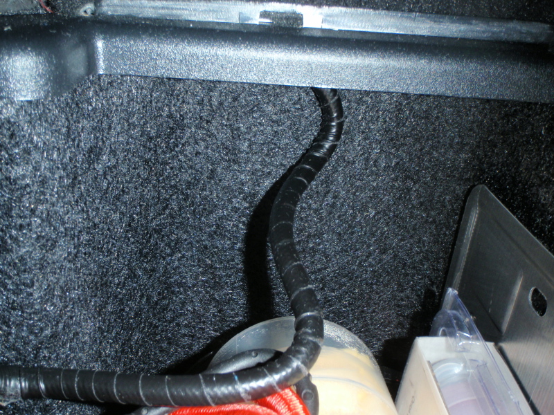
Push the side carpet back in place, hiding the XM receiver and PAL module:
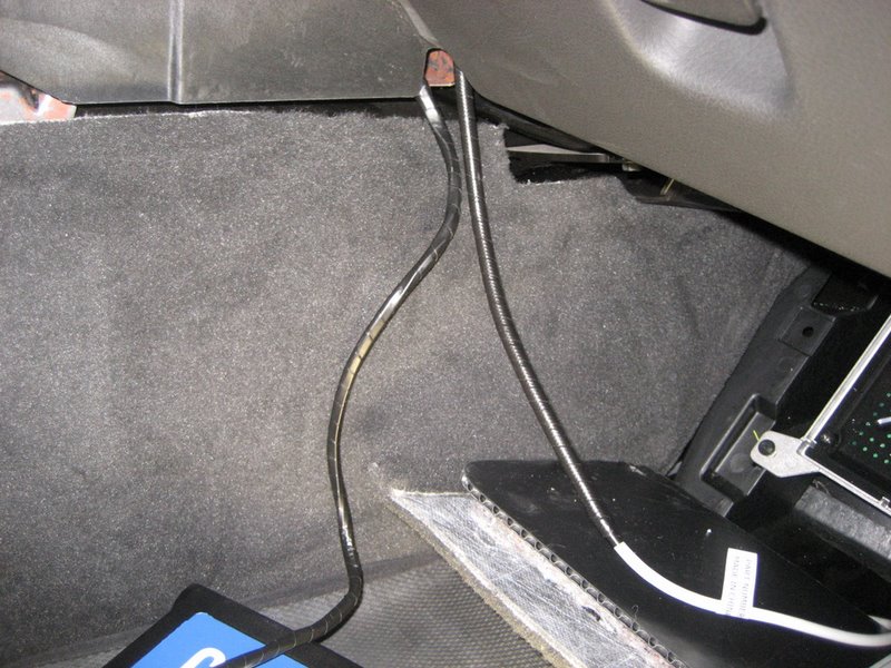
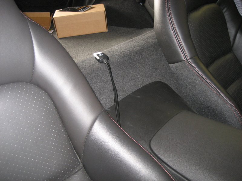
Here is the Ipod cable under the rear carpet:
Now, where do you want it to go?
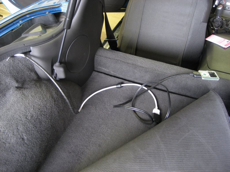
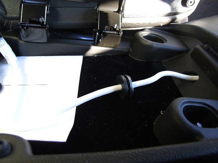
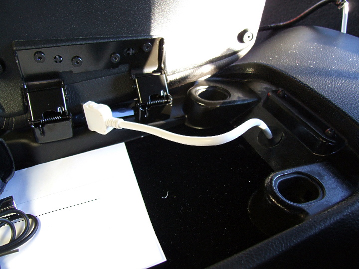
In Steve's case, he is planning to add insulation to his front area (he already completed the rear area). So he will be removing his seats and front carpet so he will decide the final location for his Ipod later. For now, he chose to run the Ipod cable between the center console and passenger seat and leave his Ipod here:
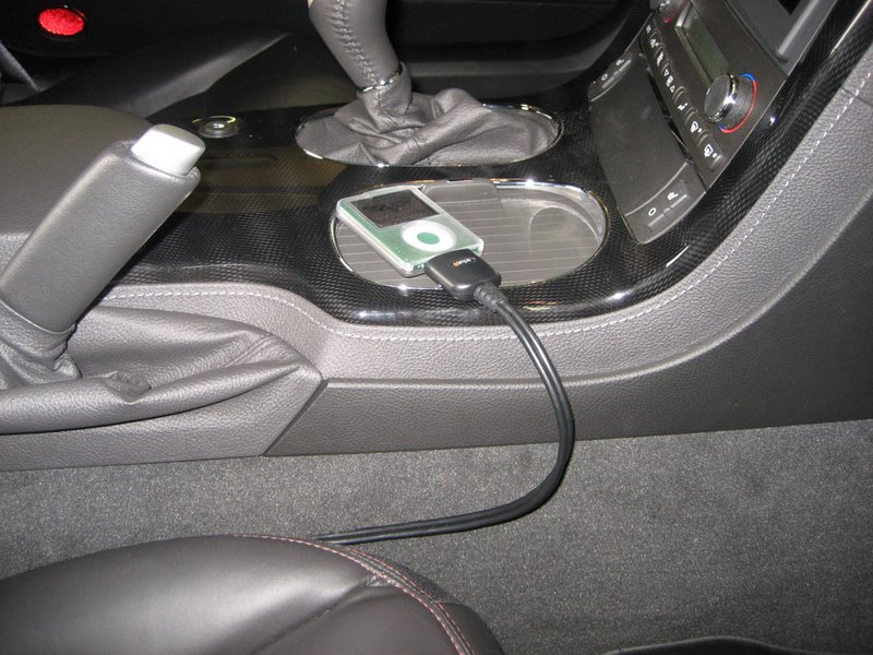
He can also place it in the console:
The console door will close easily without squashing the cable.
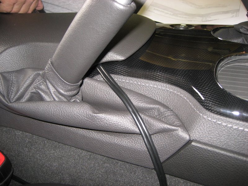
He is also thinking about later cutting a hole in the console back here and pulling the cable through:
Right now, Steve decided to leave the cable over the hump and figure out the best location later. It wouldn't be hard to route the cable under the carpet and behind the driver's seat, then between the center console and the driver's seat.
Routing the Ipod cable to your desired location is by far most of the work. But it is far easier than having to work under the dashboard and pulling the center console and Nav unit. The new harness wiring is a snap.
Update as of 12/20/09:
Here is forum member Tim McLaine's PAL installation:
The above photos show another way to install the PAL.
In this case, Tim did not need to add the iSimple extension charging adapter.
Click here for lots of Frequently Asked Questions about the PAL
A "Premium" PAL harness
Update 1/9/12
The below description below discusses my original "Premium" harness. I now have new Premium harnesses that are less expensive. Please see the Ordering Page for a description.
This started out as an interim harness to offer when I was running out of the standard harnesses, but I decided to continue to offer them as an alternative for very "picky" Corvette owners.
First of all, let me state that you don't NEED this Premium harness - how's that for a sales pitch?
It is electrically identical to the standard harness in every way. It won't make the PAL work or sound any better than the standard harness.
Here is what is different:
It is made from the original PAL harness that comes with the PAL kit. Like all GM factory harnesses, it is a fully wrapped harness for neatness and extra protection. In addition, the factory harnesses usually use name branded electrical connectors like Delphi and Yazaki. These connectors are made with heavier duty plastic and the terminals inserted into them are made to be removable with special tools. The terminals are replaceable in the event that they are damaged somehow.
The standard harnesses are not fully wrapped and they utilize generic connectors and terminals that are not made to be replaceable.
As a practical matter, once you plug in the harness to the modules you are connecting, you are likely never to even see the harness again, much less worry about replacing terminals.
Still, some Vette owners are picky and want absolute "OEM quality" in everything, and they are willing to pay a premium price for that option.
So that is why I will continue to offer this harness.
Also notice that the premium price is on an exchange basis. If you order one of these harnesses, I need you to send me your original PAL harness after you get your PAL up and running. This is to provide the basic harness that I can then modify for others.
I have to cut off and discard the four original Delphi Micro-Pack 100 connectors that fit the back of the Nav unit.
Then I reinstall a Delphi or Yazaki Micro 64 connectors in their place:
Here is the new XM connector. It is the same connector as on the PAL end of the harness:
Here is the Yazaki body harness connector:
This is where you plug the original Yazaki XM connector into:
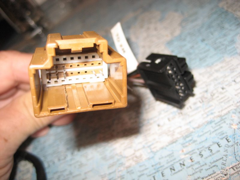
Another shot of both connectors:
Here is the PAL connector on the long end of the harness:
And the complete harness:
This harness is longer than you need for an XM receiver installation, so you must fold up the harness.
It is more suitable for a coupe/Z06 installation because there is plenty of room above the wheel well.
For a convertible installation, the shorter standard cable can be hidden a bit easier behind the waterfall.
I have a few of these available if any owners are interested.
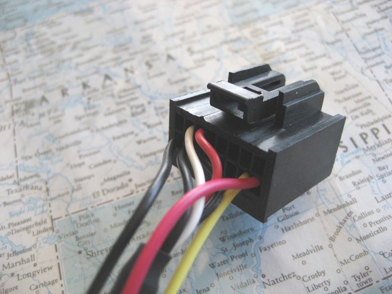
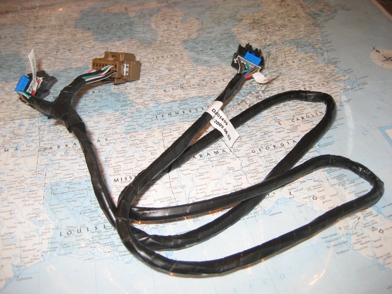
For comparison purposes, here is the original PAL harness included in the PAL kit:
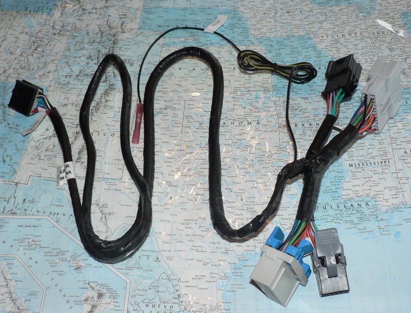
Note that this harness has four connectors (24 pin and 12 pin male and female) plus the "dreaded" XM serial data wire that is to be connected to the hidden underdash Splice Pack.
Most of the wiring between the 24 pin and 12 pin male and female connectors in the original PAL harness is only "pass-through" wiring. It has nothing to do with the PAL module itself.
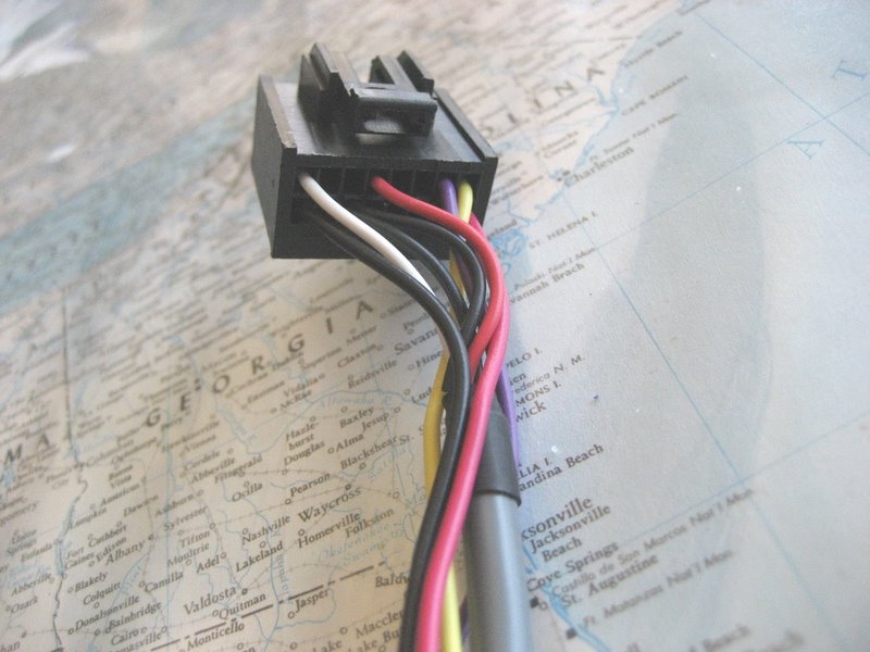
The custom harnesses for the XM receiver location replaces these four connectors with two 16 pin male and female connectors and incorporates the serial data wire into the much simplified harness.
Here is how forum member Jim Downing installed his PAL using the premium harness:
He used some extra mounting tape to be sure it holds well.
Because the premium harness is longer, it allowed Jim to install the PAL further back and a little farther away from the XM receiver:
Jim stores his Ipod in the left rear storage compartment. Here's his Ipod cable:
Click here for Ordering Information
Click here for lots of Frequently Asked Questions about the PAL
Please don't use the forum PMs because my inbox just keeps getting filled up and I have to delete the PMs.
Email is much better!